Dimensioning
Architect 3D automatically displays dimensions as you draw, making it easy to precisely place walls, doors, and other items in your plan drawing. This includes automatic dimensions, room dimensions, window/door callouts, and wall distance indicators. In some instances, you might want to view or print your plan drawing without dimension annotation. You have the option of turning off these automatic dimensions if you don’t want it displayed on the drawing page or as you draw.
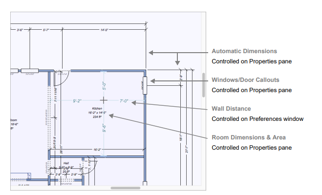
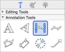
Other dimensions are drawn manually to help you measure and plan as you design. The powerful Dimension Wall Spacing Tool will be especially useful to add interactive dimensions between walls, where they are not automatically generated. Dimensions drawn with the Dimension Wall Spacing Tool are automatically updated when either wall is moved. You’ll find this tool extremely useful when measuring between the main house and the walls of other buildings, like a garden shed or playhouse. All Dimensioning tools can be found in the Annotation Tools group on the left sidebar. For information on assessing the sidebar, see “Left Sidebar”
To control automatic dimension display
- While nothing is selected in the design window, click the Properties tab and select the “Display dimensions” checkbox to enable automatic dimensions.
To disable dimensions, deselect the checkbox.
(alternatively) Choose 2D > Hide Automatic Dimensions or Show Automatic Dimensions.
To control window and door dimensions
- While nothing is selected in the design window, click the Properties tab and select the “Display callouts” checkbox to enable window and door callouts.
To disable dimensions, deselect the checkbox.
(alternatively) Choose 2D > Hide Window & Door Callouts or Show Window & Door Callouts.
To control wall distance indicators
The wall distance indicators display dimension lines from the cursor to the nearest walls when a tool is active.
 |
 |
|---|---|
Cursor Tracking Off Cursor Tracking On
1 Choose Architect 3D > Preferences. The Preferences dialog appears.
2 Click the Editing tab and, under Display Options, select the “Show wall distance indicators” checkbox to enable the dimensions.
To disable dimensions, deselect the checkbox.
3 Click Save.
To control the room label display
Room dimensions are available on the Properties pane when a room is selected in the design window.
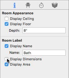
Display Name checkbox controls if the name label appears in the design window. When selected, the text in the Name field appears in the design window. When deselected, the name does not appear. You can edit the text in the field to update the name; be sure to press the Return key to accept changes.
Display Dimensions checkbox controls if the width and height measurements appear in the room label. When selected, the dimensions appear; when deselected they are hidden.
Display Area checkbox controls is the room area appears in the room label. When selected, the area appears; when deselected it is hidden.
1 In 2D Plan view, click the center of the room you want to edit. The room is highlighted in yellow.
2 Click the Properties tab on the right sidebar and, under Room Label, select the label(s) you want to show.
Deselect the label(s) you want to hide. (optional) Edit the Room Name text.
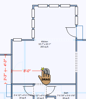
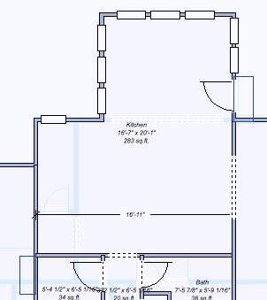
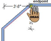
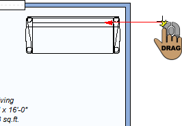
Dimension Wall Spacing
This tool quickly places a dimension between two walls. The dimension must start along a wall, but does not have to end at another wall. When you release, the dimension automatically extends to the nearest wall surface or center, depending on what you specify when the tool is active.
 |
 |
|---|---|
To place a wall-spacing dimension
1 Choose the Wall Spacing button  from the Annotation Tools group in the left sidebar.
2 On the Properties pane, choose to measure From centers or From surfaces.
3 Use the Drag-to-Size drawing method to drag the dimension in the direction of the wall you want to measure to and release to place the measurement.
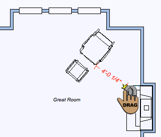
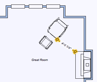
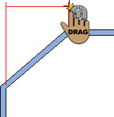
Zero-Offset Dimension
This creates dimensions from any point, surface, or object, even at angles. In the image below, we’re measuring the distance from the glider to the fireplace.
 |
 |
|---|---|
To place a zero-offset dimension
1  Choose the Zero-offset Dimension button from the Annotation Tools group in the left sidebar.
2 Use the Drag-to-Size drawing method to measure between objects.
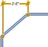
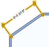
Offset Dimension
Offset dimensions are placed with the Offset Dimension Tool. This determines the horizontal or vertical distance between two points.
 |
 |
 |
|---|---|---|
To place an offset dimension
1 Choose the Offset button ! from the Annotation Tools group in the left sidebar.
2 Use the Drag-to-Size drawing method to drag the dimension from the start point of the measurement to the end point of the measurement.
3 Move the pointer in the direction you want the offset dimension to be placed and click to place the dimension.
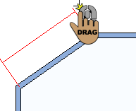
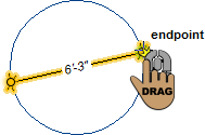
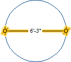
Length Dimension
This allows you to measure the distance of a single segment by selecting the two end points, the dimension is positioned offset from the segment.
 |
 |
 |
|---|---|---|
To place a length dimension
1 Choose the Length button  from the Annotation Tools group in the left sidebar.
2 Use the Drag-to-Size drawing method to drag the dimension from the start point of the measurement to the end point of the measurement.
3 Move the mouse in the direction you want the offset dimension to be placed and click to place the dimension.
Diameter Dimension
This allows you to measure the diameter of a circle by dragging along the circle’s perimeter, automatically detects the opposite edge and displays the dimension in the middle of the circle.
 |
 |
|---|---|
Note : This dimension applies to circles only; you cannot measure the diameter of an oval.
To place a diameter dimension
1 Choose the Diameter button  from the Annotation Tools group in the left sidebar.
2 Use the Drag-to-Size drawing method to drag along the edge of the circle. The dimension automatically snaps to the opposite edge of the circle.
3 Release to set the dimension.
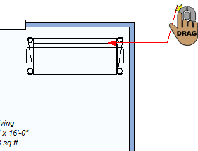
Leader Dimension
This allows you to annotate your workspace by positioning a single arrow and leader line between two objects, for example, when associating text with a 2D object. You can also automatically add a room’s area and name by pointing into an enclosed room. When you place a leader dimension on a component or object, the description is automatically detected for the annotation. You can edit this as needed.
Note : To change the leader type, see “Leader Dimension Properties”
 |
 |
 |
|---|---|---|
Once placed, you can edit the label text, including font properties and alignment, as well as change the leader type and arrowhead style. For more information, see “Leader Dimension Properties”
To place a leader dimension
1 Choose the Leader button  from the Annotation Tools group in the left sidebar.
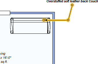
2 Position the crosshair in the design window where you want the arrow to appear and use the Drag-to-Size drawing method to set the position for the first segment of the dimension.
3 Release the mouse button and drag in the direction you want the second segment to be placed.
4 Click to set the end point and place the dimension.
Leader Dimension Properties
Leader dimensions can be customized by editing their text and alignment. You can also choose between a text label or a marker label, and customize the arrowhead style. To edit leader dimension properties, use the Selection Tool to select the dimension in the design window. Its properties are displayed on the Properties tab.
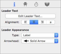
Edit Leader Text button opens a dialog with the leader text where you can edit the text and font style. For more information, see “Edit Text and Text Properties”
Alignment options allow you to set the text justification for Left, Center, Right, or Auto.
Type specifies whether the leader dimension uses a label or marker
 |
 |
|---|---|
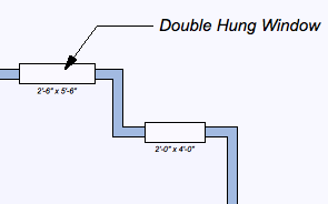
Label Marker
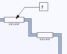
Marker displays an incremental number, with the leader text that is visible when you hover over It with your cursor. This saves space when there is a lot of text to be displayed.
Note : A list of leader markers can be printed. For more information, see “Printing Floor Plans”
Label displays the leader text in the design window.
Arrowhead specifies the arrowhead style for the selected leader dimension.