Placing Receptacles
Architect 3D makes it simple to add electrical components to your home plan. Using the convenient tabbed utility tools, simply select the components you want to place and click. Dimension lines automatically appear, making it easy to place components a specific distance from a neighboring electrical component or wall segment.
You’ll notice that when placing certain outlets and switches, the object is automatically “tracked” to the wall segment, making accurate placement simple. Floor and ceiling outlets are not tracked to walls.
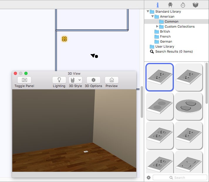
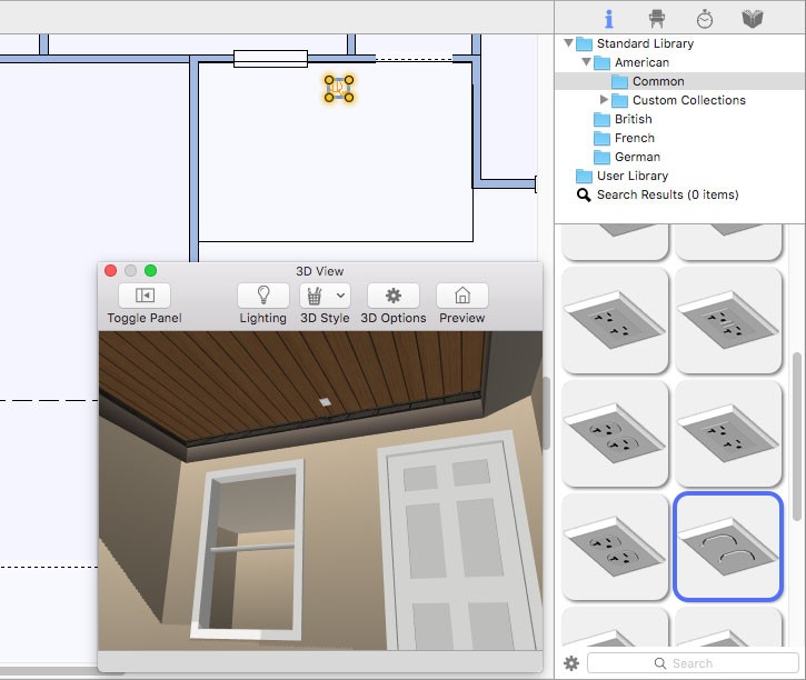
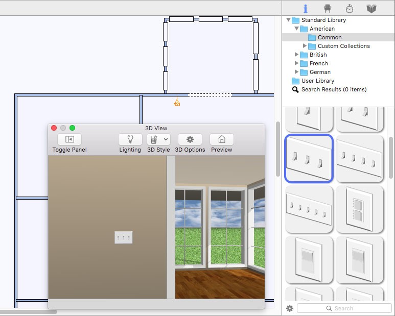
While a receptacle tool is active, or a receptacle is selected in your drawing, you can choose a receptacle style on the Properties pane in the right sidebar. From the pop-up menu, choose a Custom or Standard library and then select the style you want on the Preview Bar. The receptacle in your drawing is updated, and you can see the style in the 3D view. The Wall Receptacle library is shown here, however the Floor Receptacle and Ceiling Receptacle libraries are organized similarly. As you hover over each preview, its description is displayed.
Wall Receptacle
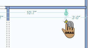
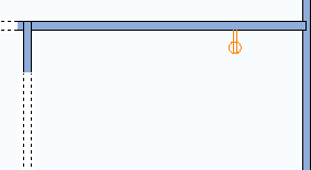
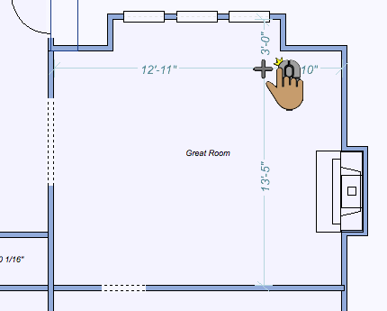
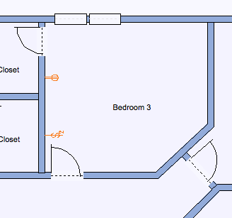
Wall receptacles are tracked along walls. Dimensions are displayed as you drag the receptacle along the wall, indicating the distance from the center of the receptacle to the nearest wall or other electrical component. You can choose the style you want on the Properties pane when the Receptacle Tool is active or a receptacle is selected in your drawing.
To place wall receptacles
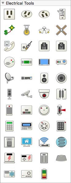
1 Choose Receptacle button  from the Electrical Tools group.
2 Use the Drag Along Wall drawing method to position the receptacle on the side of a wall where you want it and release to place.
 |
 |
|---|---|
Floor Receptacle
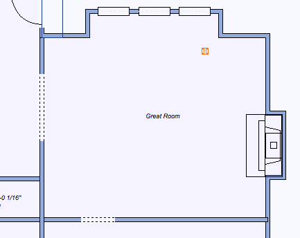
Floor receptacles are placed on the floor surface. Dimensions are displayed as you move the cursor around the design window, indicating the distance from the center of the receptacle to the nearest wall or other electrical component.
If an auto-floor is detected, the receptacle is placed at an elevation that considers the auto-floor depth. If changes are made to the auto-floor depth after a floor receptacle is placed, the receptacle’s elevation also needs to be adjusted.
You can choose the style you want on the Properties pane in the right sidebar when the Receptacle Tool is active or a receptacle is selected in your drawing.
To place a floor receptacle
1 Choose the Floor Receptacle button  from the Electrical Tools group.
2 Use the Click Once to Place drawing method to place the receptacle in your design.
 |
 |
|---|---|
Ceiling Receptacle
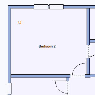
Ceiling receptacles are placed on the ceiling surface. Dimensions are displayed as you move the cursor around the design window, indicating the distance from the center of the receptacle to the nearest wall or other electrical component.
Ceiling receptacles are placed at the auto-ceiling elevation. If the ceiling for a room is disabled, it is placed at 0 by default. You can then adjust the receptacle elevation as needed.
You can choose the style you want on the Properties pane in the right sidebar when the Receptacle Tool is active or a receptacle is selected in your drawing.
To place a ceiling receptacle
1 Choose the Ceiling Receptacle button  from the Electrical Tools group.
2 Use the Click Once to Place drawing method to place the receptacle in your design.
 |
 |
|---|---|
Wall Switch
Switches are tracked along walls. Dimensions are displayed as you drag the switch along the wall, indicating the distance from the center of the receptacle to the nearest wall or other electrical component.
You can choose the style you want on the Properties tab in the right sidebar when the Switch Tool is active or a switch is selected in your drawing.
To place a switch
1 Choose the Switch button  from the Electrical Tools group.
2 Use the Drag Along Wall drawing method to position the switch on the side of a wall where you want it and release to place.
 |
 |
|---|---|