Floor Plan Image Trace
Using Floor Plan Trace, you can scan a set of drawings, for example, that you want to draw in the application. After you have scanned the plan you want to trace and saved it, you are ready to import it into Architect 3D. You can import a floor plan image to any of the available floor levels. To be sure all floors line up correctly, scan all plans at the same size and match the scale identically (see following section).
Note : You can import a plan to trace in any of the following file formats; BMP, JPG, PSD, PNG, TGA, WMF, EMF, WBMP, or PTX.
This section describes the following common tasks:
- Import a Floor Plan Image
- Match the Drawing Scale
- Show/Hide an Imported Floor Plan
Import a Floor Plan Image
Floor plan images are imported through the Design menu. After the image is imported, you can adjust the scale and then trace the image using the wall tools. After that you can continue to design by adding electrical and plumbing components, landscaping, and much more.
- For more information on adjusting the scale, see Match the Drawing Scale
- To trace walls, see “Drawing Walls”
- To add electrical features, see “Electrical Plan Tab”
- To place landscape plants, see “To add plants”
To import a floor plan image
1 Choose Design > Load Floor Plan Trace Image. A dialog appears.
2 Select the file you want to open and then click Open. The floor plan loads and appears at the center of the design window.
Match the Drawing Scale
If the floor plan is not the correct size, you can scale it in Architect 3D. This process involves creating a measurement in Architect 3D based on a known segment, wall length, or distance in your plan drawing, and then resizing the plan to match the measurement. To do this, you need to know at least one segment length or distance you can base your measurement on. Be sure to use the same scale when preparing to trace multiple floors.
Note : If you need the imported image to be larger, the percent you enter will be greater than 100%. Conversely, if you need the image to be smaller, the percent will be less than 100%.
 |
 |
|---|---|
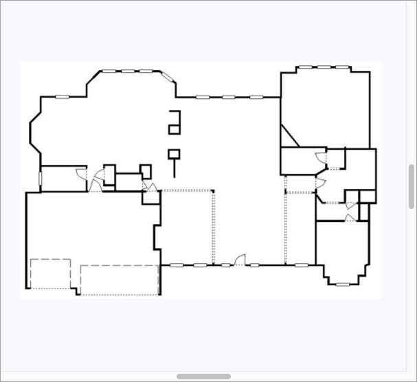
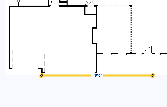
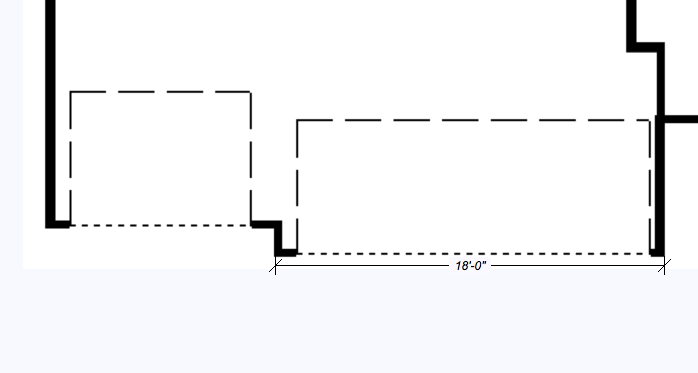
In the example above, we know the garage is 18-0 so we place a dimension as a reference and then adjust the scale until the image lines up with our dimension.
For more information on how to use the Dimension Tools, see “Dimensioning”(#_bookmark99)
To match the drawing scale
1 Import the floor plan image you want, as described in in the section “Import a Floor Plan Image”
2 Find a wall section or segment in the plan that has a known length. This is the reference point for your measurement.
3 Use one of the Dimension Tools to measure the distance of the wall section or segment in the plan by positioning the dimension parallel to the segment and extend it to match the known length on the image.
Note : It is best to measure along a longer wall to minimize the margin of error when scaling.
4 Choose Design > Resize Floor Plan Trace Image and enter values in the Horizontal Scale and Vertical Scale fields to equal amounts, to change the scale of the entire drawing in proportion, and then click OK.
Continue to adjust the percentage or dimension values until the image scale matches the dimension you have set.
Show/Hide an Imported Floor Plan
There may be times when it is easier to work on your floor plan if the tracing image is not visible. It is easy to switch the Floor Plan Trace image on and off.
To control the floor plan trace image visibility
- Choose Design > Show Floor Plan Trace Image to show the image. To hide the image, choose Design > Hide Floor Plan Trace Image.
To remove the floor place trace image
- Choose Design > Remove Floor Plan Trace Image.