While working in 3D, you will probably have to change the workplane frequently to create objects that have the correct location and orientation.
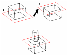
For example, create a cube based on the default workplane. If you want to create a cylinder on the top face of the cube, you must move the workplane up to this face. Then you can place the cylinder in the correct location.
The work plane can also change when you select objects, depending on whether the 2D or 3D Selector is used.
Workplane by View

Default UI Menu: Tools/New UCS/By View
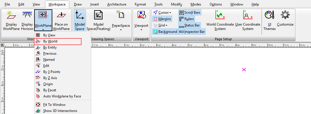
Ribbon UI Menu:
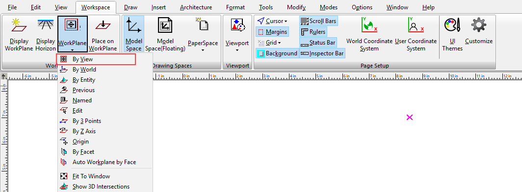
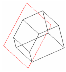
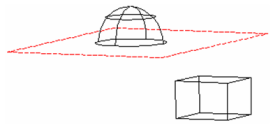
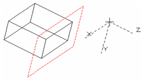
Sets the work plane according to the current view.
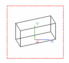
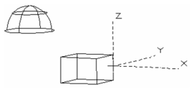
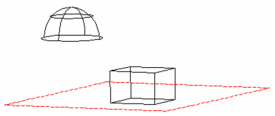
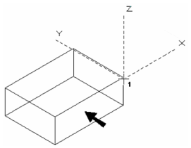
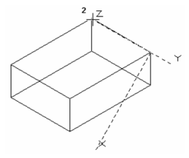
- Position the model to the desired view. In this example, the current workplane is By World.
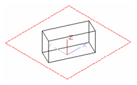
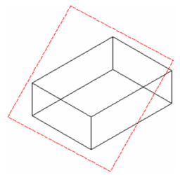
- Select By View. The work plane is turned so that it is parallel to the view plane. The Z axis becomes perpendicular to the drawing screen.
Workplane by World

Default UI Menu: Tools/New UCS/By World
Ribbon UI Menu:
Sets the work plane based on the WCS (World Coordinate System).
Note: By World is the default work plane when selecting objects that reside on different workplanes.
You can display the WCS at the lower left corner of the screen by opening the Preferences and checking Show World CS.
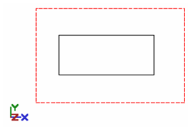
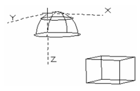
By World, top view
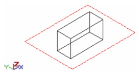
By World, Isometric_SW view
Workplane by Entity

Default UI Menu: Tools/New UCS/By Entity
Ribbon UI Menu:
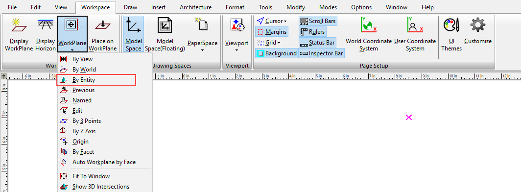
Sets the workplane according to the coordinate system of a selected object, block, or group.
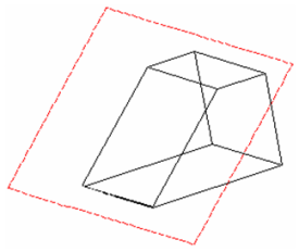
- Click By Entity, and the cursor becomes a dashed representation of the current UCS. Click the desired object.
The workplane is placed along the plane on which the object was created.
- To change the workplane to another object, use the tool again. Click the desired object.
The workplane is positioned according to the selected object.
Tip: If an object is listed in the Graphics section of the Design Director, you can set the view to an object's Workplane by Entity, and set this workplane as the current workplane. See Design Director-Graphics
Workplane by 3 Points

Default UI Menu: Tools/New UCS/By 3 Points
Ribbon UI Menu:
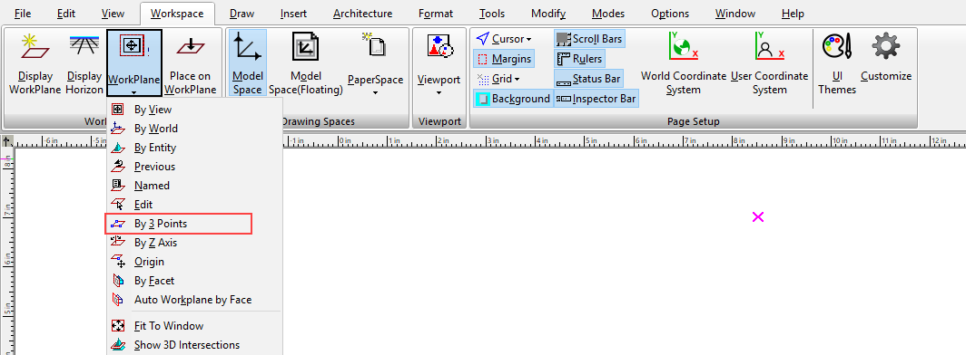
Sets the workplane to fit three points. You can select these points, or enter their coordinates in the Coordinate Fields.
- Select the UCS origin.
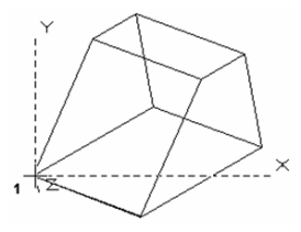
- Select the second point to define the +X direction.
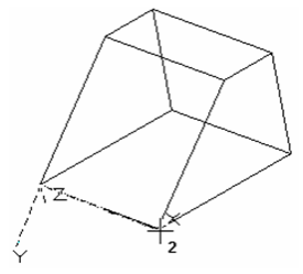
- Select any point that lies on the desired X-Y plane.
The workplane is created.
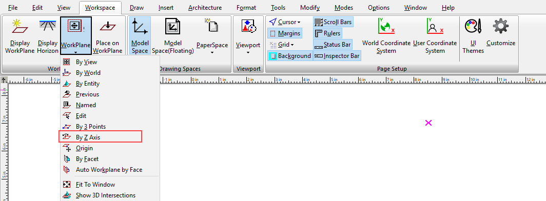
Workplane by Z axis

Default UI Menu: Tools/New UCS/By Z Axis
Ribbon UI Menu:
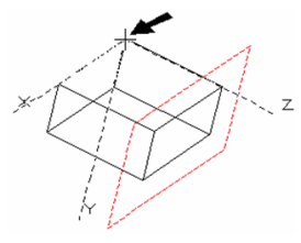
Sets the workplane by defining the Z axis of the UCS. The X-Y plane is perpendicular to this axis.
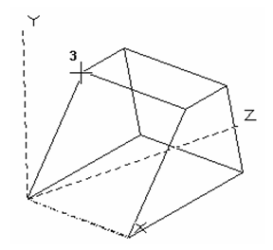
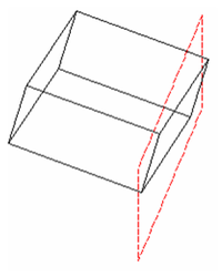
- Select the UCS origin, or enter the coordinates in the Coordinate Fields. In this example, the workplane is to be aligned with face shown.
- Select the second point to define the +Z direction.
The workplane is created.
In this example, because of the view, it may not appear that the workplane was aligned correctly. You can rotate the model to verify that the workplane is indeed aligned with the desired plane.
Workplane Origin

Default UI Menu: Tools/New UCS/Origin
Ribbon UI Menu:
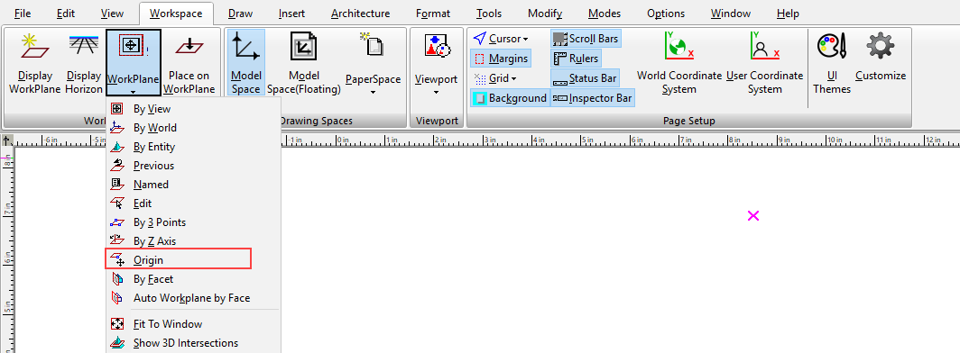
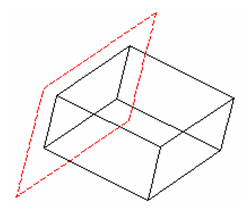
Sets the workplane parallel to (offset from) the current workplane, by relocating the UCS origin.
- When you select UCS Origin, the cursor becomes a set of dashed axes, with the X-Y plane parallel to the current X-Y workplane.
- Select a new UCS origin, or enter the coordinates in the Coordinate Fields.
The parallel workplane is created.
Workplane by Facet

Default UI Menu: Tools/New UCS/By Facet
Ribbon UI Menu:
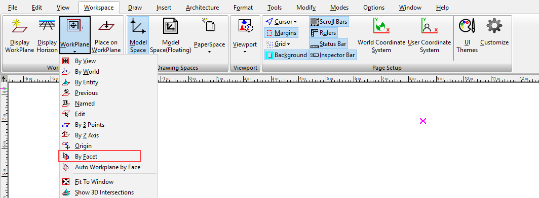
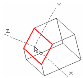
Sets the workplane to be aligned along a facet of a solid.
Note: The workplane is set to a facet automatically by default, as long as Workplane by Face mode is checked in the Drawing Aids window. You can open this window by right-clicking on the SNAP or GEO field at the bottom of the screen.
- Move the cursor to the desired facet, which is highlighted in red, and the workplane axes are displayed.
Note: To select a facet behind or in front of the indicated facet, use the Page Up and Page Down keys.
2. Click to create the workplane.