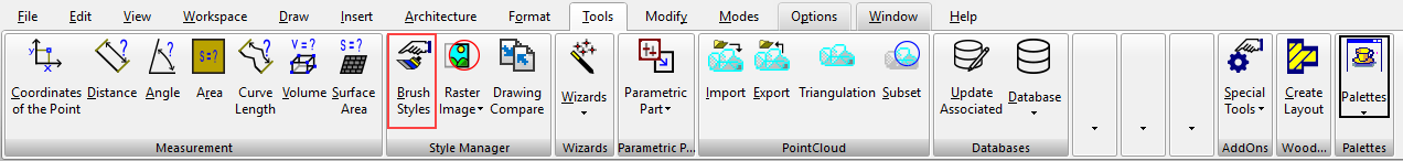
Default UI Menu: Tools/Palettes/Colors and Brushes
Ribbon UI Menu:
The Brush Styles palette appears by default in the palette area, on the right side of the screen. This tool enables you to modify existing hatch patterns and create new ones You can also define and edit bitmap and gradient patterns. Brush styles can be used to fill a closed 2D object, either by using an object's Brush Properties or by Hatching.
Note: You can use this tool to update existing patterns. Select the hatch, bitmap, or gradient pattern, make the changes, and click Update. Return to the drawing, and the fill will update in each object where it appears. If the update is not immediate, click the object in Select mode.
Hatch Patterns
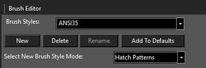
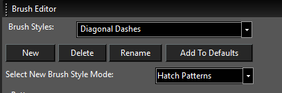
You can use Brush Styles to edit existing hatch patterns and create new ones. As an example, select Hatch Patterns for Brush Style Mode and set the Brush Style to ANSI35.
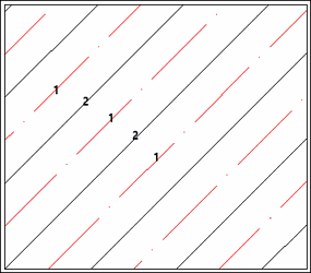
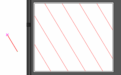
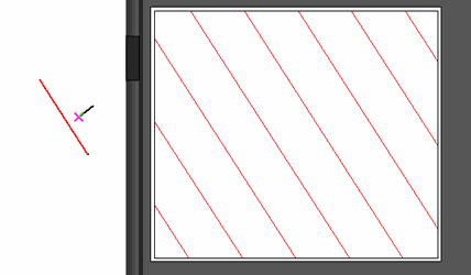
 This style consists of two Patterns - each pattern is a line that repeats at constant offsets. Highlight each pattern number to see the line highlight in red below, in the Preview area.
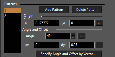
In this case, Pattern 1 is the dashed line and Pattern 2 is the unbroken line.
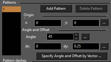
 To edit a Pattern line, you can change its Origin Point manually, or click the 3-dot icon to select an origin on-screen. You can set the Angle and Offset values the same way. If you click Specify Angles and Offset by Vector, you can define two vectors on-screen: the first defines the angle of the line, and the second defines the spacing between repeating lines. Highlight Pattern 1 (the dashed line), and you can see that it consists of four patterns.
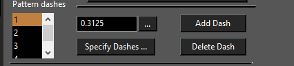
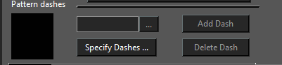
Dashes are always defined in pairs; odd numbers represent the line segments and the even numbers represent the dashes. The length value for dashes is always negative. Specify Dashes is used to create a dashed pattern from an unbroken line. Use Add Dashes and Delete Dashes to modify the dash pattern. You can update pattern lengths manually or use the 3-dot icon to define length on-screen. The following example shows how to define a new hatch pattern.
- At the top of the palette, click New and enter a new name for the hatch pattern.
-
The new pattern will be based on whatever pattern was active when the new pattern was created (ANSI35 in this case). Click Delete Pattern so that only one pattern line remains.
-
Click Specify Angle and Offset by Vector.
- Draw a line on-screen that has the angle you want in the pattern. You can snap to existing points or draw a free-form line.
- Next, draw a line on-screen that defines the offset between repeating lines.
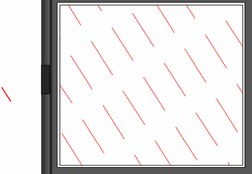
- To make this a dashes line, click Specify Dashes.
- The first line on-screen defines the length of the line segment of the dashed pattern. Be sure to define this length in the same direction you used to create the original pattern line.
-
The next vector defines the length of the dash, resulting in two dash patterns. If you want more dash patterns, always in pairs, continue defining vectors in the same direction.
-
Create more patterns and dashes as needed to get the entire pattern.
When the style is defined, click Update Style to use it in the current drawing, or Add to Defaults to be able to use it in future drawings.
Bitmap Patterns
Enter the name of the style at the top of the palette.
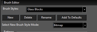
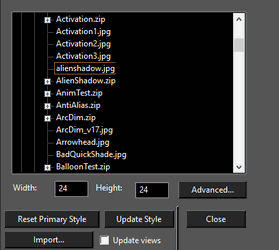
In the middle section, use the browser to locate the image file you want to use. A preview of the image appears in the lower section. The size of the repeating image is controlled by the Width and Height values. You can change these values manually, or click Advanced for more control.
Gradient Patterns
Enter the name of the style at the top of the palette.
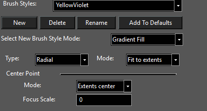
There are four types of gradient fills: Linear, Radial, Reflected, Diamond, and Custom. Each type is explained later in this section. Mode (called Fit Mode in the Brush Properties):
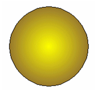
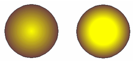
Exact Fit: The gradient completely fills the object itself. In this example, the fill completely reaches the second gradient color at the boundary of the circle.
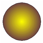 Fit to Extents: The gradient completely fills the extents rectangle that encloses the object. In this example, the second gradient color is only reached at the boundary of the extents rectangle, which is larger than the circle itself. This is why the color at the circle boundary is lighter than in the example above.
Center Point:
Modes: Select Extents center to center the fill at the center of the object's extents rectangle. Reference point centers the fill at the object's reference point (see Components of Select Edit Mode).
Focus Scale: This must be a value between 0 and 1. Zero means the color interpolation start from the center (left image below). A value of 0.5 will start the interpolation halfway between the center and the edge (right image below).
Note: Settings for Fit Mode, Center Point, and Focus Scale are set here as the fill defaults. These values can be overridden for filled objects by modifying the object's Brush Properties.
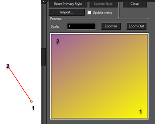
Linear Gradient Linear fill moves from one color to the other along a straight vector. Under Control Points, highlight First and set the Color. Do the same for Second. By default, the First color runs vertically along the left side and changes to the Second color along a left-to-right vector. To change this vector, click the icon with the three dots. Define the new vector on the screen. The first point of the vector controls where the First color appears.
 Radial Gradient
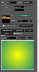
Radial fill moves from one color to the other along a radial path. Under Control Points, highlight Center and set the center color. Highlight Radius and set the outer color. Set the radius manually, or click the 3-dots icon and set the radius on-screen.
Radial Gradient
Radial fill moves from one color to the other along a radial path. Under Control Points, highlight Center and set the center color. Highlight Radius and set the outer color. Set the radius manually, or click the 3-dots icon and set the radius on-screen.
 Reflected Gradient
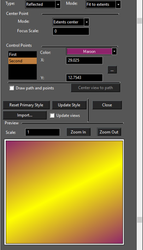
Reflected fill consists of one line of reflected color, fading to another color on either side. moves from one color to the other along a radial path. Under Control Points, highlight First and set the reflective color. Highlight Second and set the fade color.
Set the angle of the reflection line manually, or click the 3-dots icon and set the direction on-screen.
Reflected Gradient
Reflected fill consists of one line of reflected color, fading to another color on either side. moves from one color to the other along a radial path. Under Control Points, highlight First and set the reflective color. Highlight Second and set the fade color.
Set the angle of the reflection line manually, or click the 3-dots icon and set the direction on-screen.
 Diamond Gradient
Diamond fill moves from from the center outward in four directions, each separated by 90 degrees. Under Control Points, highlight Center and set the color of the center and linear patterns. Highlight Radius-Vector and set that appears in between the Center color lines.
By default, the Center color runs vertically and horizontally to either side. To change this vector, click the icon with the three dots.
Define the new vector on the screen. The first point of the vector controls where the Center color appears. The second point of the vector controls the angle of the four lines.
Diamond Gradient
Diamond fill moves from from the center outward in four directions, each separated by 90 degrees. Under Control Points, highlight Center and set the color of the center and linear patterns. Highlight Radius-Vector and set that appears in between the Center color lines.
By default, the Center color runs vertically and horizontally to either side. To change this vector, click the icon with the three dots.
Define the new vector on the screen. The first point of the vector controls where the Center color appears. The second point of the vector controls the angle of the four lines.
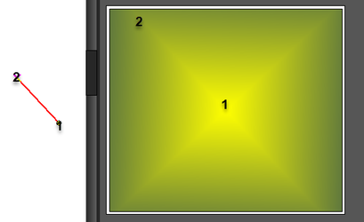 Custom Gradient
Use this type to create a custom polyline and apply colors to each polyline point. The results will resemble a Diamond Gradient, but can have numerous points, each with its own color. Color 1 runs from the center outward to each point. By default there are three other points (triangular polyline). To change the polyline, click the icon with the three dots.
Custom Gradient
Use this type to create a custom polyline and apply colors to each polyline point. The results will resemble a Diamond Gradient, but can have numerous points, each with its own color. Color 1 runs from the center outward to each point. By default there are three other points (triangular polyline). To change the polyline, click the icon with the three dots.
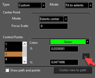 Define the polyline on the screen, proceeding in the order of Color 2, Color 3, and so on. The polyline automatically closes, and cannot intersect itself. Press space bar to finish. You can also select an existing polyline from the drawing; click the arrow icon in the Inspector Bar to do this.
If the polyline has more than three points, the number of Control Points increases, and you can set a color for each point.
Define the polyline on the screen, proceeding in the order of Color 2, Color 3, and so on. The polyline automatically closes, and cannot intersect itself. Press space bar to finish. You can also select an existing polyline from the drawing; click the arrow icon in the Inspector Bar to do this.
If the polyline has more than three points, the number of Control Points increases, and you can set a color for each point.
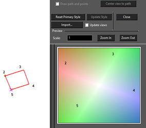 When the style is defined, click Update Style to use it in the current drawing, or Add to Defaults to be able to use it in future drawings.