(Available only in Platinum)
Default UI Menu: Modify/Modify 3D Objects/Extract Entity
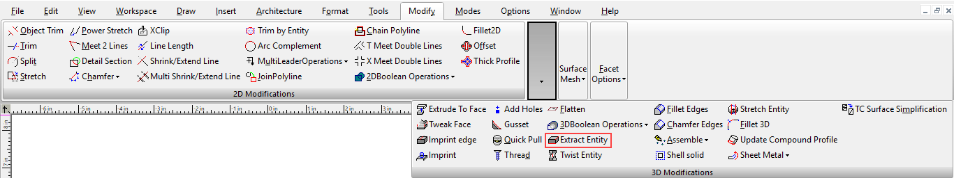
Ribbon UI Menu:
The extract Extract Entity is used to derive 2D elements from 3D ACIS solids and to modify ACIS surfaces/sheet bodies.
ACIS surfaces/sheet bodies result when non-closed objects, such as a line segment, are extruded, revolved or swept. They can also be created from ACIS Solids by using thetool, or by using the tool on a closed 2D object, and by using the this tool.
Modes:
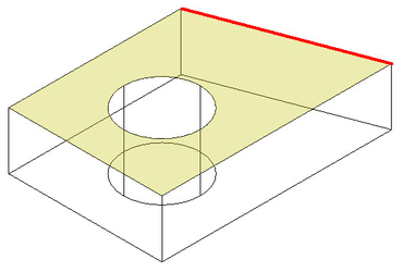
Extract Edge
In this mode the tool is used to extract an edge from a 3D entity. To extract an edge:
-
Select the Extract Entity tool.
-
Select the Extract Edge mode from the Inspector bar or Local menu.
-
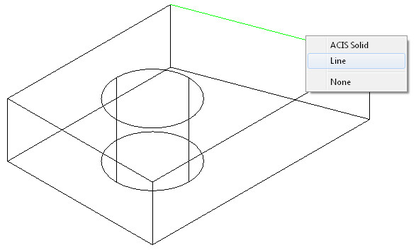
Hover over the edge you wish to extract, and click on it.
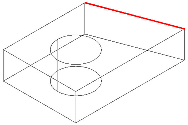
Result:
Options:
Extract Loop from Seed Edge and Face: When this option is on you can extract all connected edges on a selected face of the 3D object. Note: a Loop is the closed sequence of edges that bound a face. To extract an edge loop:
-
Select the Extract Entity tool.
-
Select the Extract Edge mode from the Inspector bar or Local menu.
-
Select the Extract Loop from Seed Edge and Face option from the Inspector bar or Local menu.
-
Hover over the face you wish to extract from, and click on it.
- Hover over the edge on the loop you wish to extract, and click on it.
Result:
Remove Open Gap
In this mode the tool is used to remove holes in ACIS surfaces/sheet bodies. To remove an open gap:
-
Select the Extract Entity tool.
-
Select the Remove Open Gap mode from the Inspector bar or Local menu.
-
Hover over the edge of the hole you wish to remove, and click on it.
Result:
To remove an open gap with the Remove All Open Gaps option.:
-
Select the Extract Entity tool.
-
Select the Remove Open Gap mode from the Inspector bar or Local menu.
-
Select the Remove All Open Gaps option from the Inspector bar or Local menu.

- Hover over the object with the holes you wish to remove, and click on it.
Result:
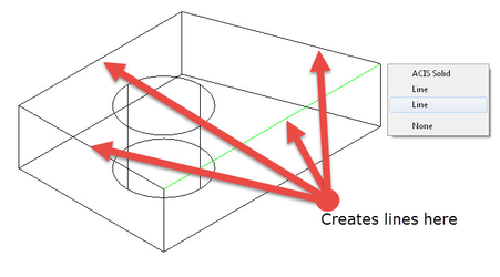
Extract Face
In this mode the tool is used to extract a face from a 3D entity. To extract a face:
-
Select the Extract Entity tool.
-
Select the Extract face mode from the Inspector bar or Local menu.
-
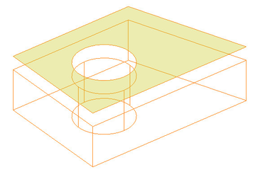
In the Inspector bar specify the Offset Distance at which the new sheet body will be created.

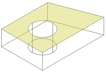
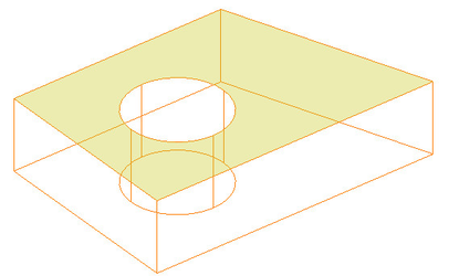
- Hover over the face you wish to extract, and click on it.
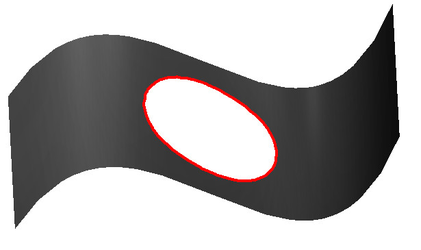
Offset Face Loop
In this mode the tool is used to extract a face from a 3D entity by offsetting a closed loop around the hole in an object. This only works with ACIS surfaces/sheet bodies. To Offset a face loop:
-
Select the Extract Entity tool.
-
Select the Offset Face Loop mode from the Inspector bar or Local menu.
-
In the Inspector bar specify the Offset Distance at which the new sheet body will be created. Negitive values will make the hole larger, and positive values will make the hole smaller.

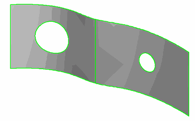
- Hover over the face you wish to offset from, and click on it.
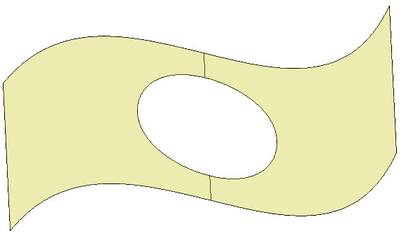
- Hover over the edge of the hole you wish to offset, and click on it.

Result using a negative value (-0.25) as the offset.
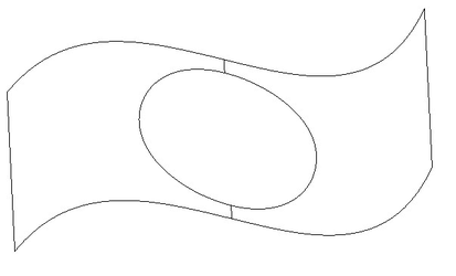
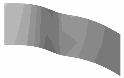
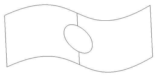
Result using a positive value (0.25) as the offset.
Options:
- Delete source object: When selected the original object will be deleted.
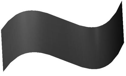
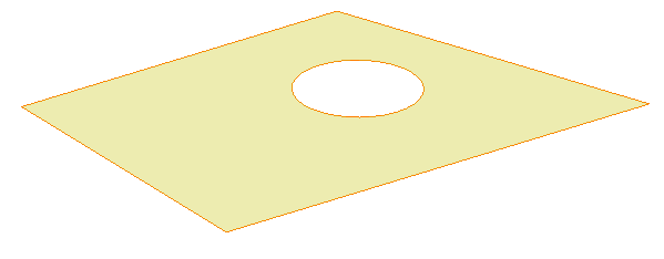
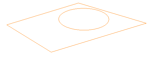
Offset Planar Face Loops
In this mode the tool is used to extract a face from a 3D entity by offsetting a the closed loops around the bounding the plane of the object. This only works with ACIS surfaces/sheet bodies. To Offset a face loop:
-
Select the Extract Entity tool.
-
Select the Offset Planar Face Loop mode from the Inspector bar or Local menu.
-
In the Inspector bar specify the Offset Distance at which the new sheet body will be created. Negitive values will make the hole larger, and positive values will make the hole smaller.

- Hover over the face you wish to offset from, and click on it.
Options:
- Delete source object: When selected the original object will be deleted.
- Rounded corners: When selected the exterior corners (relative to the offset direction) will be rounded.