(Available only in Pro Platinum)
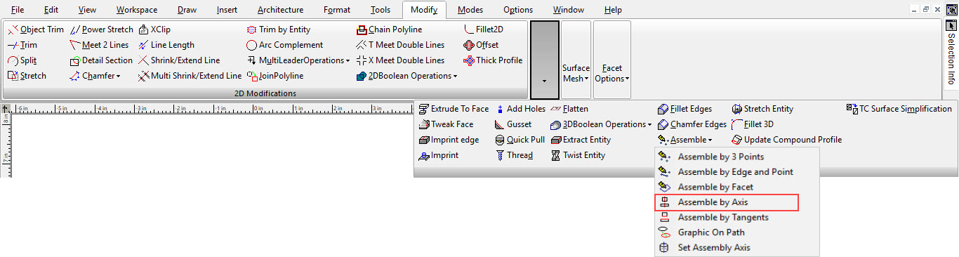
Default UI Menu: Modify/Modify 3D Objects/3D Assemble/Assemble by Axis
Ribbon UI Menu:
Changes the position of an object by aligning axes.
Assembling Circular or Rotated Objects
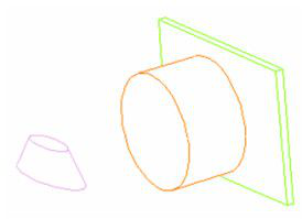
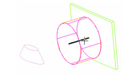
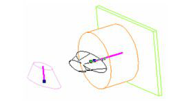
For round objects that have a rotational axis (such as Cylinder, Cone, Polygonal Prism, Revolve, or Simple Extrude based on a circular 2D object), you need to set the assembly axis before the objects can be assembled. This example will assemble a truncated cone based on an ellipse, aligning it with the axis of a cylinder.
-
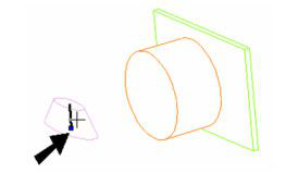
Activate Set Assembly Axis.
-
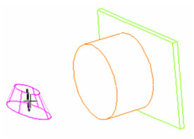
Click one of the round objects (the truncated cone, in this case). Its axis is displayed as a dashed line.
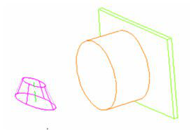
- Click the axis to define it for the assembly.
-
Select Finish from the Inspector Bar or local menu.
-
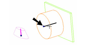
Do the same to define the axis for the other round object (the cylinder).
-
Select Finish from the Inspector Bar or local menu.
-
Activate Assemble by Axis. Click the axis of the object you want to move. Be sure to select the axis near the endpoint that will meet the endpoint of the other axis.
- Click the destination axis, near the endpoint where the other axis will meet it.
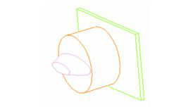
A preview of the moved object appears. You can move it in either direction along the axis.
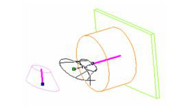
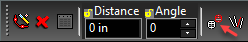
- Use the mouse or enter the move distance. If you want to rotate the object, you can enter an Angle. If the moved object is oriented backward, select Turn Over from the local menu or Inspector Bar.
- To rotate it with the mouse, select Rotate. If you turned or rotated the object, the preview will update.
- When the distance and angle are defined, the object moves so that the two axes are aligned.
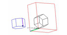
Assembling Planar or Linear Objects
For objects that have no assembly axis defined, you can define the axis during the assembly process. This example uses a polygonal prism and a box.
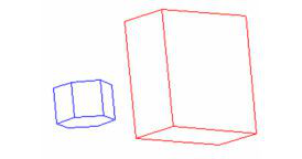
- Activate Assemble By Axis, and select Use Any Line from the local menu or Inspector Bar.
- Select the object you want to move. Then click a line or edge you want to use as the assembly axis. Be sure to click near the endpoint of the axis which will meet the other axis.
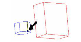
- Click an edge or line as the destination axis. Select it near the endpoint that will meet the other axis. A preview of the moved object appears. You can move it in either direction along the axis.
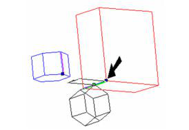
- Use the mouse or enter the move distance. If you want to rotate the object, you can enter an Angle. If the moved object is oriented backward, select Turn Over from the local menu or Inspector Bar.
- To rotate it with the mouse, select Rotate. If you turned or rotated the object, the preview will update.
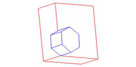
- When the distance and angle are defined, the object moves so that the two axes are aligned.
Distance by faces, Angle by faces and Angle by axes
Make sure to create sufficient axes to setup for these modes. Make two axes of two bodies coincident, then select one of modes by using hot keys or local menu
Distance by Faces
- Select the Distance by faces mode.
- Define the first face on the body which will be moved.
- Define destination face
- The body will be moved by the distance between selected faces along the common axis and two faces will become coincident.
Angle by Faces
- Select face on body you want to rotate.
- Select the second face (on any body) you wish the first face to to be parallel to.
- If the rotation around the common axis is available, then the normals of the two defined faces will become coincident/parallel.
Angle by Axes
Mode 1:
- Select the second axis on first body; the one you are moving.
- Select the second axis on the body you are aligning to.
- If the rotation around the common axis is available, the directions of selected axes will become coincident.
Mode 2:
- Select the second axis on first body; the one you are moving.
- Select the second axis on the body you are aligning to.
- If the rotation around the common axis is available, the directions of selected axes will become coincident.