(Available in all TurboCAD Variants)
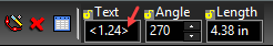
Creating dimensions involves two basic steps: selecting the objects to be measured, and locating the dimension. By default the magnitude of the dimension is calculated automatically and is recorded as the dimension text, measured in current World units. (Leader dimensions, which contain text labels, are the exception to this rule.) You can override the default text of a dimension by specifying the text in the Inspector Bar prior to finishing the dimension.
 You can also change the dimension text in the dimension's Properties, by changing the Attributes field of the General page.
Note: To create several types of dimensions automatically in one step,
When Auto Add Constraints is active, any dimensions you assign are created as variables that appear in the Calculator Palette.

Dimension variables can be constrained to other dimensions, or to other variables or numbers. This is particularly powerful when used in conjunction with Auto Constraints .
Orthogonal Dimension
Creates a horizontal or vertical dimension.
Note: To create orthogonal dimensions automatically,
- Select the first point.
- Select the second point, or enter the length and angle of the dimensioned line in the Inspector Bar.
- For a horizontal dimension, move the mouse above or below the two points and click to define the location. You can also enter the length of the witness lines in the Inspector Bar.
- For a vertical dimension, define the dimension at either side of the two points.
Local menu options: Segment Dimensioning, Entity Dimensioning Horizontal / Vertical Mode only: creates either type of dimension, no matter where the dimension is located.
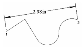
Parallel Dimension
Creates a dimension showing the absolute length of an object.
Note: To create parallel dimensions automatically,
- Select the first point.
- Select the second point, or enter the length and angle of the dimensioned line in the Inspector Bar.
- Move the mouse and click to define the location. You can also enter the length of the witness lines in the Inspector Bar.
For any two endpoints, the absolute length is parallel to the line between the points.
Local menu options: Segment Dimensioning, Entity Dimensioning
Distance Dimension
Sets two lines parallel to one another and places a constrained dimension between them. For this tool to be available, Auto Add Constraints must be on.
Note: To create distance dimensions automatically,
- Select the two lines, or select them by snapping to either of their endpoints.
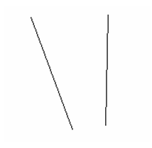
- Place the dimension, and the lines are made parallel.
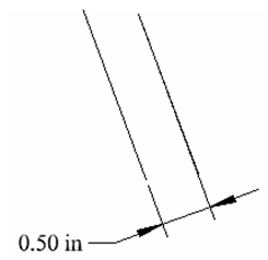
Note:Because Auto Add Constraints is on, the Distance dimension appears as a variable in the Calculator Palette and can be edited.
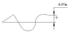
Rotated Dimension
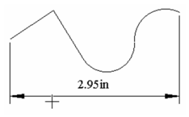
Creates a dimension projected in a specified direction.
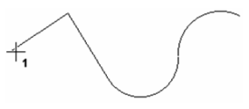
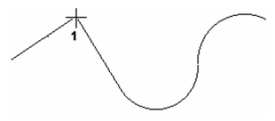
- Select two points to define the dimension's direction. The dimension will be measured normal to this line. You can also define the first point, then specify the angle of the vector in the Inspector Bar.
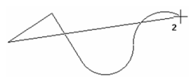
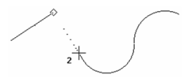
- Select the first point of the object to be dimensioned. Select the second point, or enter the length and angle of the dimensioned line in the Inspector Bar.
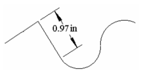
- Move the mouse and click to define the location. You can also enter the length of the witness lines in the Inspector Bar.
Local menu options: Segment Dimensioning, Entity Dimensioning: Available only after the dimension direction has been defined.
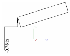
Datum Dimension
Creates a dimension showing the horizontal or vertical distance from a point. By default, the point is the absolute origin, but you can change this.
- Select the point whose distance from the origin is to be displayed. A rubberband line appears, indicating the origin of the dimension.
- To display the Y coordinate (horizontal dimension text), move the mouse to either side of both the origin and the selected point, and click to locate the dimension. You can also enter the angle and length of the extension lines in the Inspector Bar.
- To display the X coordinate (vertical dimension text), move the mouse above or below both the origin and the selected point.
Local menu options: Set Origin: By default, datum dimensions are created relative to the absolute origin. Use Set Origin to select a new origin. This origin will remain in effect until changed.
Baseline Dimension
Creates a series of parallel linear dimensions that follow the axis of an existing linear dimension.
- Select an existing linear base dimension. Click near the side you want to serve as the baseline. A temporary rectangle appears at the baseline end.
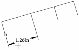
- Select the first point where you want a new baseline dimension.
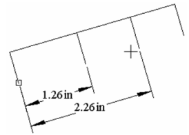
- Continue selecting points. Each new baseline dimension will be created at an offset from the previous one.
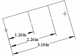
Note: The offset distance is controlled by the Baseline Increment value on the Advanced Format page of the Properties window.
When finished, select Cancel from the local menu or press Esc. Local menu option: Select Dimension: Select a new base dimension.
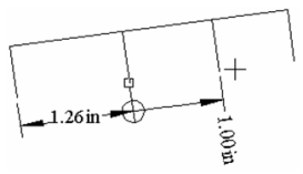
Continuous Dimension
Creates a series of parallel linear dimensions measured from the previous dimension. The dimensions follow the axis of the base dimension.
- Select an existing linear base dimension. Click near the side you want the next dimension to be created. A temporary rectangle appears at the baseline end.
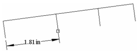
- Select the first point where you want a new continuous dimension.
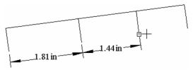
- Continue selecting points. Each new continuous dimension will be measured from the previous dimension.
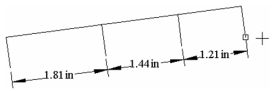
- When finished, select Cancel from the local menu or press Esc.
Local menu option: Select Dimension: Select a new base dimension.
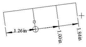
Incremental Dimension
Creates a series of parallel linear dimensions measured from the previous dimension. The dimensions follow the axis of the base dimension, and are displayed normal to the axis.
- Select an existing linear base dimension. Click near the side you want the next dimension to be created. A temporary rectangle appears at the baseline end.
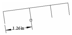
- Select the first point where you want a new incremental dimension.
- Continue selecting points. Each new incremental dimension will be measured from the previous dimension.
- When finished, select Cancel from the local menu or press Esc.
Local menu option: Select Dimension: Select a new base dimension.
Angular Dimension
Creates dimensions measuring angles. You can dimension the angle between two lines, the angle of an arc, between two points of a circle, and between a node and two points.
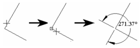
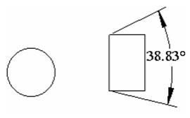
Angle Between Two Lines
-
Select the two lines.
-
Move the mouse to dimension the acute or obtuse angle. Click to locate the dimension, or enter the length and angle in the Inspector Bar.
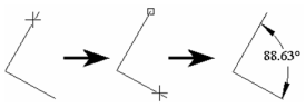
Be careful where you select the lines. If you select close to the angle vertex, you could dimension the complementary angle.
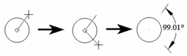
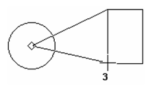
Angle within a Circle
- Select the circle.
- Select the start angle, or enter the angle in the Inspector Bar.
- Select the end angle.
- Move the mouse to dimension the acute or obtuse angle. Click to locate the dimension, or enter the length and angle in the Inspector Bar.
Angles of an Arc
- Select the arc.
- Move the mouse to dimension the acute or obtuse angle. Click to locate the dimension, or enter the length and angle in the Inspector Bar.
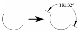
Note: If Arc Length is checked in the Format page of the Properties window, the arc length will be dimensioned instead of the angle.
Local menu option: Angle Node (freeform angle): Dimensions an angle by selecting the angle vertex then two points.
- Select the angle vertex.
- Select two points defining the angle.
- Move the mouse to dimension the acute or obtuse angle. Click to locate the dimension, or enter the length and angle in the Inspector Bar.
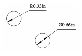
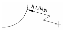
Radius - Diameter Dimension
Dimensions the radius or diameter of an arc or circle.
- Select the arc or circle.
2. Move the mouse and click to locate the dimension, or enter the length and angle in the Inspector Bar.
Local menu option: Large Radius: If the arc center is out of your drawing space, use this option to display the dimension from outside.
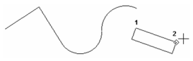
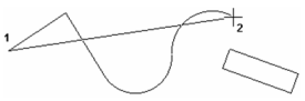
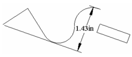
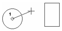
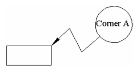
Leader
Creates dimension text attached to a simple line leader pointing to a location in your drawing. The leader is similar to a polyline.
Note: Check Draw as Spline on the Advanced Format page of the Properties window to create a curves leader rather than line segments.
- Enter the text in the Inspector Bar.
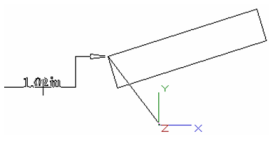
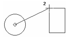
- Select the leader start point (the end with the arrow). Select or more additional segment endpoints, or enter the length and angle of each segment in the Inspector Bar.----
Note: The arrowhead is defined by Arrowheads / 1st on the Format page of the Properties window.----
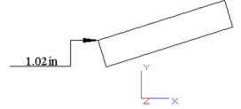
3. Double-click to finish, or select Finish from the local menu, or press Alt+F.
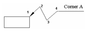
A text box can be created, by selecting one from the Advanced Format page of the Properties window.
Wall Dimensions
There is a special tool for dimensioning walls created via the Architecture tools.