Eleven types of RedSDK luminances are provided you can create and edit any of the following using the Render manager.
Ambient Light
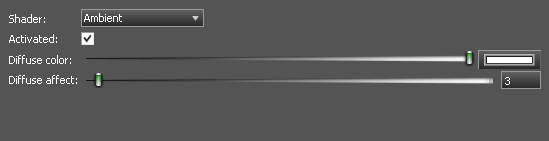
An ambient light adds a constant omni-directional light source. The primary reason to use ambient lighting is to lighten a scene or avoid getting a totally blacked-out scene. PARAMETERS
- Diffuse color – Sets the diffuse color of the light.
- Diffuse affect – Sets the relative intensity (power) of the diffused light.
Beam Light
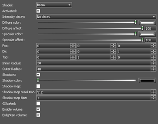
 A Beam light shines a along the direction defined by Dir. It has a radial factor defined by Inner Radius and Outer Radius. Between the two radii values, the light intensity smoothly decreases.
PARAMETERS
A Beam light shines a along the direction defined by Dir. It has a radial factor defined by Inner Radius and Outer Radius. Between the two radii values, the light intensity smoothly decreases.
PARAMETERS
- Intensity decay – Set the rate at which the lights power diminishes.
- Diffuse color – Sets the diffuse color of the light.
- Diffuse affect – Sets the relative intensity (power) of the diffused light.
- Specular color – Sets the specular color of the light.
- Specular affect – Sets the relative intensity (power) of the Specular light.
- Pos – Sets the X,Y,Z position of the light relative to the object to which it is attached.
- Dir – Sets the X,Y,Z direction of the light relative to the position.
- Top – Defines a second axis which is perpendicular to the direction, used for the rotation, if the lights display is not circular.
- Inner Radius – Sets the inner radius for the light.
- Outer Radius – Sets the outer radius for the light.
- Shadows – Sets whether the light will generate shadows, or not.
- Shadow Color – Specifies the color of shadows created by the light.
- Shadow Map – Shadow maps are generated by testing whether or not each specific pixel is visible from the light source. This accomplished by comparing each pixel to a depth image (z-buffer) of the light source's view, stored in the form of a texture file. Shadow maps can accelerate the rendering of shadows, but usually as the cost of some quality.
- Shadow Map Resolution – Sets the resolution of the shadow map. Values must be a multiples of 2.
- Shadow Map Blur – Sets a blur factor on the shadow map, reducing jagged edges and transitions.
- Enable volume– Enable the light to interact with Volumetric effects
- Enlighten volume– Enable the light to illuminate with Volumetric effects
Directional Light
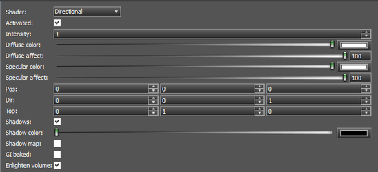
A Directional light shines a along the direction defined by Dir. and continues infinitely in that direction and at the same intensity. Directional lights can't cast shadow maps. Beam lights are also directional lights but that are able to use shadow mapping. PARAMETERS
- Intensity – Set the intensity of the light.
- Diffuse color – Sets the diffuse color of the light.
- Diffuse affect – Sets the relative intensity (power) of the diffused light.
- Specular color – Sets the specular color of the light.
- Specular affect – Sets the relative intensity (power) of the Specular light.
- Pos – Sets the X,Y,Z position of the light relative to the object to which it is attached.
- Dir – Sets the X,Y,Z direction of the light relative to the position.
- Top – Defines a second axis which is perpendicular to the direction, used for the rotation, if the lights display is not circular.
- Shadows – Sets whether the light will generate shadows, or not.
- Shadow Color – Specifies the color of shadows created by the light.
- Shadow Map – Shadow maps are generated by testing whether or not each specific pixel is visible from the light source. This accomplished by comparing each pixel to a depth image (z-buffer) of the light source's view, stored in the form of a texture file. Shadow maps can accelerate the rendering of shadows, but usually as the cost of some quality.
- GI Baked – Supports GI baking.
- Enlighten volume – Enable the light to illuminate with Volumetric effects
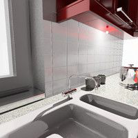
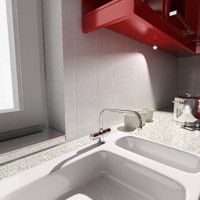
Physical Light
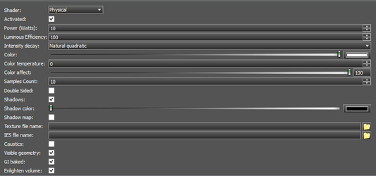
A physical light source - shaped as a rectangle in this specific example A physical light uses the definition of light sources from physical parameters issued from lamp manufacturers. A physical light is associated to a mesh ( The 3D Object associated with the Luminance) that defines the light surface that will emit light in the scene. Therefore a physical light can be of any shape. Physical lights are rendered on the CPU using sampling and are approximated on the GPU. There are two possible approximations for a physical light on the GPU:
- If the physical light is linked to a rectangular mesh, then the physical light is automatically turned into an Area light.
- If the physical light is linked to a mesh with any other geometric shape, then the physical light is automatically turned into a Point light.
Physical lights only support ray-traced shadows on the CPU. Physical lights converted to point lights are set to use ray-traced shadows (shadow maps for point lights can be expensive and are disabled in this case). Physical lights converted to area lights area set to use ray-traced shadows either. PARAMETERS
- Power – Sets the power of the light in Watts.
- Luminous Efficiency – luminous efficiency of the light in percentage (%).
- Intensity decay – Set the rate at which the lights power diminishes.
- Color – Sets the color of the light.
- Color Temperature – Alternate color value which supports definition of the color by temperature in Kelvin.
- Color Affect – Sets the relative intensity (power) of the color light.
- Samples Count – Sets the maximum number of light samples.
- Shadows – Sets whether the light will generate shadows, or not.
- Shadow Color – Specifies the color of shadows created by the light.
- Texture File Name – Rather than using a single constant color for the whole light, you can setup a texture from which light color will be read. Using a texture, you can simulate projectors or complex light filters.
- IES File Name – Manufacturers measure the behavior of their bulbs and store their directional contribution into IES files. Those files are available for most of the bulb models directly from the manufacturers' web sites. Even if IES files store information about the shape of the emitter, they are not used here.
- Caustics – Specifies whether the light will generate caustic effects.
- Visible Geometry - Specifies whether the physical geometry of the associate 3D objects will be seen.
- GI Baked – Supports GI baking.
- Enlighten volume – Enable the light to illuminate with Volumetric effects
Point Light
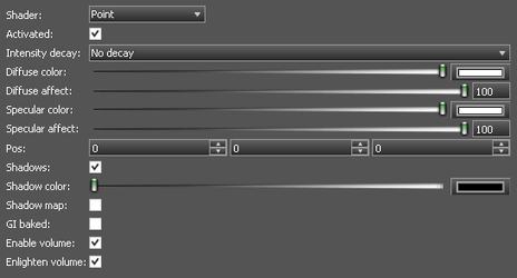
 The point light is a centric light. It produces an lighting in all directions around the point light.
PARAMETERS
The point light is a centric light. It produces an lighting in all directions around the point light.
PARAMETERS
- Intensity decay – Set the rate at which the lights power diminishes.
- Diffuse color – Sets the diffuse color of the light.
- Diffuse affect – Sets the relative intensity (power) of the diffused light.
- Specular color – Sets the specular color of the light.
- Specular affect – Sets the relative intensity (power) of the Specular light.
- Pos – Sets the X,Y,Z position of the light relative to the object to which it is attached.
- Shadows – Sets whether the light will generate shadows, or not.
- Shadow Color – Specifies the color of shadows created by the light.
- GI Baked – Supports GI baking.
- Enable volume – Enable the light to interact with Volumetric effects
- Enlighten volume – Enable the light to illuminate with Volumetric effects
Rectangular Area Light
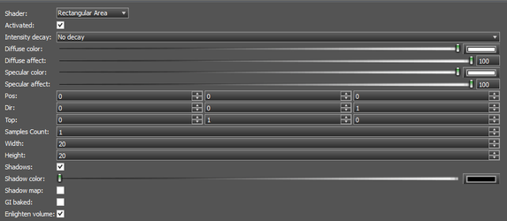 Area light sources are surface lights that emit light from a rectangle.
PARAMETERS
Area light sources are surface lights that emit light from a rectangle.
PARAMETERS
- Intensity decay – Set the rate at which the lights power diminishes.
- Diffuse color – Sets the diffuse color of the light.
- Diffuse affect – Sets the relative intensity (power) of the diffused light.
- Specular color – Sets the specular color of the light.
- Specular affect – Sets the relative intensity (power) of the Specular light.
- Pos – Sets the X,Y,Z position of the light relative to the object to which it is attached.
- Dir – Sets the X,Y,Z direction of the light relative to the position.
- Top – Defines a second axis which is perpendicular to the direction, used for the rotation, if the lights display is not circular.
- Samples Count – Sets the number of samples used to populate the light surface. Must be greater than 0.
- Width – Sets the width of the defining rectangle.
- Height – Sets the height of the defining rectangle.
- Shadows – Sets whether the light will generate shadows, or not.
- Shadow Color – Specifies the color of shadows created by the light.
- GI Baked – Supports GI baking.
- Enlighten volume – Enable the light to illuminate with Volumetric effects
Rectangular Physical Light
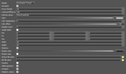
A Physical Rectangle light uses the definition of light sources from physical parameters issued from lamp manufacturers. A Physical Rectangle light uses a rectangle that defines the light surface that will emit light in the scene. Physical lights are rendered on the CPU using sampling and are approximated on the GPU. There are two possible approximations for a physical light on the GPU:
- If the physical light is linked to a rectangular mesh, then the physical light is automatically turned into an Area light.
- If the physical light is linked to a mesh with any other geometric shape, then the physical light is automatically turned into a Point light.
Physical lights only support ray-traced shadows on the CPU. Physical lights converted to point lights are set to use ray-traced shadows (shadow maps for point lights can be expensive and are disabled in this case). Physical lights converted to area lights area set to use ray-traced shadows either. PARAMETERS
- Power – Sets the power of the light in Watts.
- Luminous Efficiency – Sets the luminous efficiency of the light in percentage (%).
- Intensity decay – Set the rate at which the lights power diminishes.
- Color – Sets the color of the light.
- Color Temperature – Alternate color value which supports definition of the color by temperature in Kelvin.
- Color Affect – Sets the relative intensity (power) of the color light.
- Samples Count – Sets the maximum number of light samples.
- Pos – Sets the X,Y,Z position of the light relative to the object to which it is attached.
- Dir – Sets the X,Y,Z direction of the light relative to the position.
- Top – Defines a second axis which is perpendicular to the direction, used for the rotation, if the lights display is not circular.
- Samples Count – Sets the number of samples used to populate the light surface. Must be greater than 0
- Width – Sets the width of the defining rectangle.
- Height – Sets the height of the defining rectangle.
- Shadows – Sets whether the light will generate shadows, or not.
- Shadow Color – Specifies the color of shadows created by the light.
- Texture File Name – Rather than using a single constant color for the whole light, you can setup a texture from which light color will be read. Using a texture, you can simulate projectors or complex light filters.
- IES File Name – Manufacturers measure the behavior of their bulbs and store their directional contribution into IES files. Those files are available for most of the bulb models directly from the manufacturers' web sites. Even if IES files store information about the shape of the emitter, they are not used here.
- Caustics – Specifies whether the light will generate caustic effects.
- Visible Geometry - Specifies whether the physical geometry of the associate 3D objects will be seen.
- GI Baked – Supports GI baking.
- Enlighten volume – Enable the light to illuminate with Volumetric effects
Spherical Physical Light
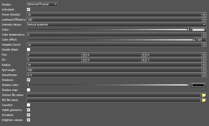
- Luminous Efficiency – luminous efficiency of the light in percentage (%).
- Intensity decay – Set the rate at which the lights power diminishes.
- Color – Sets the color of the light.
- Color Temperature – Alternate color value which supports definition of the color by temperature in Kelvin.
- Samples Count – Sets the maximum number of light samples.
- Pos – Sets the X,Y,Z position of the light relative to the object to which it is attached.
- Dir – Sets the X,Y,Z direction of the light relative to the position.
- Spot Angle – the spot half-angle. In the cone whose apex is at the light's source position, headed at Dir, of Spot angle , the light radial intensity is pow(cos(angle(L,S)),Radial intensity decay).
- Shadows – Sets whether the light will generate shadows, or not.
- Shadow Color – Specifies the color of shadows created by the light.
- Shadow Map – Shadow maps are generated by testing whether or not each specific pixel is visible from the light source. This accomplished by comparing each pixel to a depth image (z-buffer) of the light source's view, stored in the form of a texture file. Shadow maps can accelerate the rendering of shadows, but usually as the cost of some quality.
- Texture File Name – Rather than using a single constant color for the whole light, you can setup a texture from which light color will be read. Using a texture, you can simulate projectors or complex light filters.
- IES File Name – Manufacturers measure the behavior of their bulbs and store their directional contribution into IES files. Those files are available for most of the bulb models directly from the manufacturers' web sites. Even if IES files store information about the shape of the emitter, they are not used here.
- Caustics – Specifies whether the light will generate caustic effects.
- Visible Geometry - Specifies whether the physical geometry of the associate 3D objects will be seen.
- GI Baked – Supports GI baking.
- Enlighten volume – Enable the light to illuminatewith Volumetric effects
Sky Light
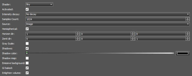
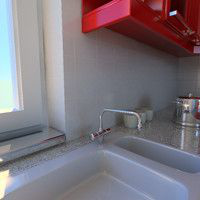
This physical skylight shape generates a light source that casts light from a dome surrounding the scene. In addition a skylight shape can create a physical sky texture that can be used in the rendering for direct visibility. A physical skylight shape is rendered on the CPU and is rendered by a sampled skydome on the GPU. The GPU rendering of the skylight is a good approximation of the real physical skylight rendered on the CPU. PARAMETERS
- Intensity decay – Set the rate at which the lights power diminishes.
- Samples Count – Sets the maximum number of light samples.
- Hemispherical – When On the generated map will cover a hemisphere, Off the generated map will cover a whole sphere.
- Shadow Map – Shadow maps are generated by testing whether or not each specific pixel is visible from the light source. This accomplished by comparing each pixel to a depth image (z-buffer) of the light source's view, stored in the form of a texture file. Shadow maps can accelerate the rendering of shadows, but usually as the cost of some quality.
- Shadows – Sets whether the light will generate shadows, or not.
- Shadow Color – Specifies the color of shadows created by the light.
- GI Baked – Supports GI baking.
- Enlighten volume – Enable the light to illuminate with Volumetric effects
Spot light
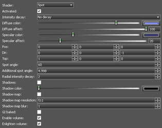
The spot light source is a centric light. It produces an isotropic lighting in all directions issued from the spot cone apex. The lighting emitted by the spot light decreases at the spot cone borders. A spot light is defined in a two steps code:
- Intensity decay – Set the rate at which the lights power diminishes.
- Diffuse color – Sets the diffuse color of the light.
- Diffuse affect – Sets the relative intensity (power) of the diffused light.
- Specular color – Sets the specular color of the light.
- Specular affect – Sets the relative intensity (power) of the Specular light.
- Pos – Sets the X,Y,Z position of the light relative to the object to which it is attached.
- Dir – Sets the X,Y,Z direction of the light relative to the position.
- Top – Defines a second axis which is perpendicular to the direction, used for the rotation, if the lights display is not circular.
- Width – Sets the width of the defining rectangle.
- Height – Sets the height of the defining rectangle.
- Shadows – Sets whether the light will generate shadows, or not.
- Shadow Color – Specifies the color of shadows created by the light.
- Shadow Map – Shadow maps are generated by testing whether or not each specific pixel is visible from the light source. This accomplished by comparing each pixel to a depth image (z-buffer) of the light source's view, stored in the form of a texture file. Shadow maps can accelerate the rendering of shadows, but usually as the cost of some quality.
- Shadow Map Resolution – Sets the resolution of the shadow map. Values must be a multiples of 2.
- Shadow Map Blur – Sets a blur factor on the shadow map, reducing jagged edges and transitions.
- Spot Angle – the spot half-angle. In the cone whose apex is at the light's source position, headed at Dir, of Spot angle , the light radial intensity is pow(cos(angle(L,S)),Radial intensity decay).
- Additional Spot Angle – beyond the Spot angle cone, the radial intensity smoothly drops to 0.0 at the Spot angle + Radial intensity decaylimit angle.
- Radial intensity decay – intensity decay within the main cone area.
- Shadows – Sets whether the light will generate shadows, or not.
- Shadow Color – Specifies the color of shadows created by the light.
- Enable volume – Enable the light to interact with Volumetric effects
- Enlighten volume – Enable the light to illuminatewith Volumetric effects
Sun
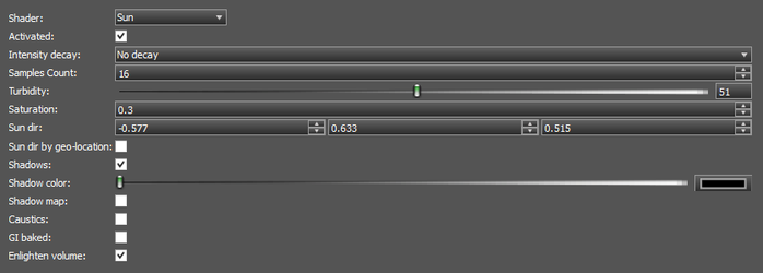
- Intensity decay – Set the rate at which the lights power diminishes.
- Samples Count – Sets the maximum number of light samples.
- Turbidity – Sets the amount of particles present in the atmosphere. The valid range of turbidity values is [Integer: 0, 100].
- Saturation – Sets the saturation factor applied to each pixel in the texture. Set it to 1.0 to create a texture with vivid colors. The valid range of values is [0, 1].
- SunDir – sets direction to the sun relative to the associated 3D object.
- Shadows – Sets whether the light will generate shadows, or not.
- Shadow Color – Specifies the color of shadows created by the light.
- GI Baked – Supports GI baking.
- Shadow Map – Shadow maps are generated by testing whether or not each specific pixel is visible from the light source. This accomplished by comparing each pixel to a depth image (z-buffer) of the light source's view, stored in the form of a texture file. Shadow maps can accelerate the rendering of shadows, but usually as the cost of some quality.
- Caustics – Specifies whether the light will generate caustic effects.
- GI Baked – Supports GI baking.
- Enlighten volume – Enable the light to illuminate with Volumetric effects
Intensity decay
A light source in the Red engine may have a decay of its intensity, based on the distance between the lit point and the light source center. The lit point is always the geometrical point at the pixel center of the lit pixel. A light source may have a center or not. If it has no center, then it does not support the intensity decay calculation. NONE Intensity is 1 for the entire light source effect area. Inverse Linear Intensity linearly decreases as the lit point moves away from the light. INTENSITY = IMAX / DISTANCE; where IMAX = ATT[0]. Inverse Quadratic Intensity decreases using a quadratic equation as the lit point moves away from the light. INTENSITY = IMAX / POW(DISTANCE,2); where IMAX = ATT[0]. Inverse Cubic Intensity decreases using a cubic equation as the lit point moves away from the light. INTENSITY = IMAX / POW(DISTANCE,3); where IMAX = ATT[0]. Inverse Linear Quadratic Intensity decreases using a ratio between the current distance to the lit point and a reference distance. INTENSITY = 1 - POW(DISTANCE / DMAX,2); where DMAX = ATT[0]. Quadratic Relative Distance Intensity uses a 2nd order equation: INTENSITY = 1 / ( 1 + KLIN * DISTANCE + KQUA * DISTANCE); where ATT[0] = KLIN and ATT[1] = KQUA. No Decay 3DSMax 3DSMax decay. Near and far attenuation distances can be used, and the intensity does not vary with the distance besides that. INTENSITY = 1. Inverse Linear 3DSMax 3DSMax decay. Near and far attenuation distances can be used, and the intensity decreases using the following equation: INTENSITY = min( 1, DREF / D ); where DREF = ATT[0]. Inverse Quadratic 3DSMax 3DSMax decay. Near and far attenuation distances can be used, and the intensity decreases using the following equation: INTENSITY = min( 1, POW(DREF / D,2) ); where DREF = ATT[0].