(Available in Pro Platinum)
Controls the format of dimensions. You can set the properties for all dimensions, or for just a single dimension.
Text
There is no Text page in dimension Properties, but parameters can be set in the Selection Info palette. For details on Text parameters.
Format
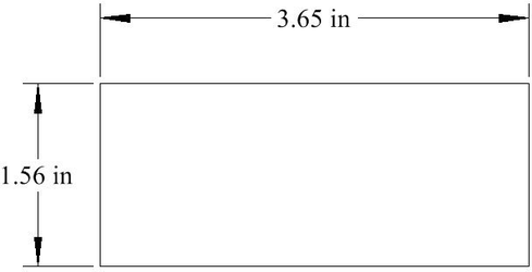
Controls the shape of dimension arrows and the position of text relative to the dimension line.
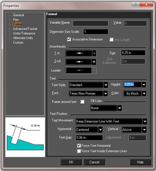
Variable Name and Value: If the dimension is produced as a result of Auto Dimensions (most commonly used together with Auto Constraints), the dimension will have a variable name and value assigned to it. This value appears in Properties / Format window, as well as the Calculator Palette.
Dimension Size Scale: The scaling factor for displaying the dimension. Arc Length: Available for Angular dimension, displays the arc length rather than degree measurement. Associative Dimension: Checked by default. Associative dimensions retain their positions and the dimension text will update when their associated object changes. To tell whether a dimension is associative, select the object. Any dimension associated with the object will be colored blue.
Note: This parameter is only available when setting the default properties of dimension tools. You will not see it in the Properties window for a selected dimension. This parameter must be set before the dimension is created.
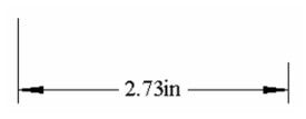
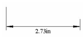
Arrowheads:
1st and 2nd: Select arrow shapes for the start and end of the dimension.
Leader: Select the arrow shape for leader dimensions.
Size: Length of the arrowhead or diameter of the dot
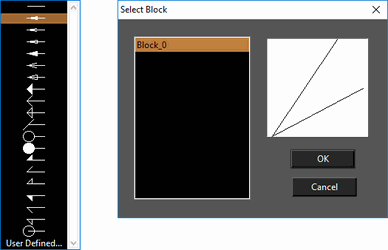
Tick Extension: specify the length of the tick extension line. You can specify a custom user defined arrowhead. User defined arrow heads are based by selecting a block.
Text:
Text Style: Select the Text style for the dimension. Text styles are specified in the Style Manager. Height: Sets the height of the dimension text. Font: Specifies the font use in the dimension text. Color: Sets the color of the dimension text. Frame around text: Draws a rectangular frame around the dimension text. Fill Color: Specifies a color which will fill the text frame. The options are: None, Background and Custom. Background fills the frame with the background color. Custom allows you to select a color. Text Position: Controls the dimension text position: Text Movement: These options control how the dimension text is moved when editing the dimension. Horizontal: Select the text alignment with respect to witness lines. The preview window displays each option. Options vary for dimension and leader text.
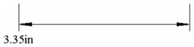
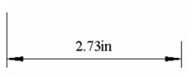
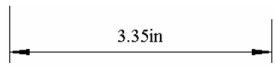 Dimensions - Centered
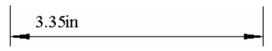
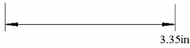
Dimensions - First Extension Line
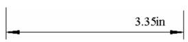
Dimensions - Second Extension Line
 Dimensions - Over First Extension Line
 Dimensions - Over Second Extension Line
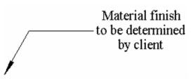
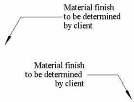 Leaders - Default Justification(Depends on the leader orientation)
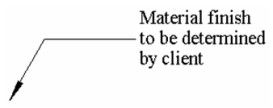
 Leaders - Center Justification
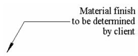
 Leaders - Left Justification
 Leaders - Right Justification
Vertical: Select the text alignment with respect to the dimension/leader line. Outside places the text on the side of the dimension/leader line opposite the selected dimension/leader points.
Leaders - Right Justification
Vertical: Select the text alignment with respect to the dimension/leader line. Outside places the text on the side of the dimension/leader line opposite the selected dimension/leader points.
 Above
Above
 On Line
 Outside
Text Gap: The distance between the dimension text and the dimension line. Adjustment: Available for VerticalOnLine position, The distance of the text above or below the dimension line. A value of zero (default) will place the text on the same level as the dimension line. Higher values move the text above the line; lower (negative) values move the text below the line. Force Text Horizontal: Makes the dimension text horizontal no matter how the dimension is rotated. Force Text Inside Extension Line: Keep dimension text between the extension lines, regardless of the distance between the extension lines. If unchecked, the system will decide where to place text.
Non-Rotatable Text
With a dimension (or dimension tool) selected, you can go to the Selection Info palette, and under the Text-Transformation area you can specify that the text be non-rotatable.
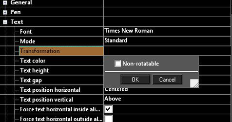
When text is set to non-rotatable it will always face the user no matter the orientation of the drawing.
Advanced Format
Options for drawing and scaling the dimension and extension lines.
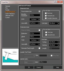
Dimension Line:
The line over which the dimension text is located. Force Interior Line: If checked, the dimension will have an interior dimension line even if the text is outside the extension lines. If unchecked, the interior dimension line will be drawn only if the dimension text is inside the extension lines. Baseline Increment: The distance between each dimension in a series of baseline dimensions. Do not Draw: Options for omitting parts of the dimension line. Color: Sets the color of the dimension line. Line Width: Sets the Line width for the dimension line. Line Type: Specifies the line type for the dimension line.
Extension Line:
Lines that connect the dimension line to the object being dimensioned. Draw as Spline: If checked, the Leader tool will use a spline rather than a line to attach the dimension text to the corresponding drawing location. See Splines and Bezier Curves Extension: The length of the extension line segments that extend outward beyond the dimension lines. Offset: The distance between the extension lines and the dimensioned object. Do not Draw: Options for omitting parts of the extension lines. Color: Sets the color of the extension lines. Line Width: Sets the line width for the extension lines. Line Type: Specifies the line type for the extension lines. Generate Fixed-Length – Use the Length field to fix the length of the maximum drawn length for extension lines. Length - Specify the length used by the Generate Fixed-Length property.
Leader Text Frame:
Available only for Leader dimensions. Select a shape for the closed line bounding the dimension text. Size: When Circle or Quadrate is selected for the text box, define the box size. Fit to Text: Check if you want the text box to fit the dimension text.
Units - Tolerance
Parameters for formatting the appearance of dimension text, and for controlling the display of tolerance - the allowable deviation from the dimension.
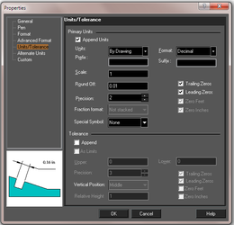
Primary Units:
Append Units: If checked, the dimension text will display its unit. Units: If Append Units is checked, select the desired units. Format: Options for how the dimension text is displayed (decimal, feet, radians, surveyor, etc.) As of version 2015 the Format setting can now be set to By Drawing. This means the format used will be the one globally specified on Options | Space Units Prefix, Suffix: Add a prefix and/or a suffix to the dimension text. (Not available for Leader dimensions.) Scale: Change the scale of the value displayed by the dimension text relative to World units. For example, if you enter a value of 0.1, the dimension will display a value of 0.1 inch when dimensioning a distance of 1 inch in World units. The default value for the linear measurement scale is 1.
Note: You will probably want to leave Scale unchanged, unless you have an inset in your drawing that uses a different scale than the rest of your drawing.
Round Off: -The decimal place to which the dimension text will round off. If you type a value of 0.1, for example, the text will be rounded off to tenths. Special Symbol: Prepends a symbol to the dimension text. The options include: None, Diameter, Degree, and Plus Minus. Precision: The level of accuracy, represented by a number between 1 and 10. Trailing Zeros: is set to 4, and and Round Off is set to 4, the dimension text will read 2.3400.
Note: Trailing Zeros, Round Off, and Precision are interrelated, and need to be considered as a group when establishing dimension settings. If Round Off is less than Precision, dimension text may not accurately reflect the exact measurement. If Round Off is greater than Precision, then Trailing Zeros will show the additional available precision if Trailing Zeros is set to a value equal to Precision. For most applications, Precision and Round Off should be set to the same level (a Precision of 4 is the same as a Round Off of 0.0001). Trailing Zeros should then be used if necessary to display the level of precision in use. Trailing Zeros is not applicable when fractions are used.
Leading Zeros: For dimensions of less than one unit, a zero will appear at the beginning of the dimension. For example: 0.5 feet, as opposed to .5 feet. Zero Feet, Zero Inches: Relevant for architectural and engineering units. For dimensions less than one foot or one inch, the zero will appear as a placeholder. For example: 0'-0 1/4" as opposed to 1/4".
Tolerance:
Append: If checked, the dimension text will include a tolerance. As Limits: If checked, the dimension will be shown as a pair of values defining the limits of the dimension value. Relative Height: The height of the tolerance relative to the rest of the dimension text. Upper, Lower: Values for positive and negative tolerance. The remaining tolerance parameters are the same as for Primary Units.
Alternate Units
Alternate units are a secondary set of units for each dimension, such as 1" [25.4mm].
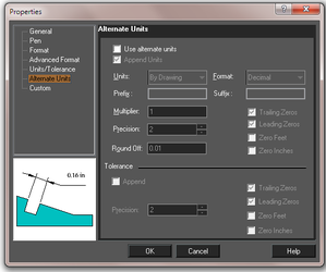 Use alternate units: If checked, the dimension and/or tolerance will be displayed with a value in alternate units, in square brackets following the primary dimension. The parameters are the same as on the Units / Tolerance page.