Pattern
Note: TurboCAD has several defined patterns, but if you want to apply your own image as a pattern.
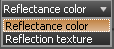
The next set of parameters in the Render Manager is for the material's pattern. First there are two options: color or texture.
 If set to color, that color will be the diffusion color of the material.

If a texture map is selected, the mapped image will be used to color the material.
Image/texture Maps
texture maps are images used in pattern, reflection, transmission and bump to establish the pattern of the effect. All texture maps are assumed to be square. If the image used is not square it will be stretched/compacted into a square texture map, possibly deforming the texture.
The size of all texture maps is equal to one unit of the currently defined Space Unit in the Model space. For example if the Space Unit is set to inches the all texture maps are 1in. by 1in. If the Space Unit is in millimeters then the texture map is 1mm. by 1mm. The resulting texture can then be modified by scaling.
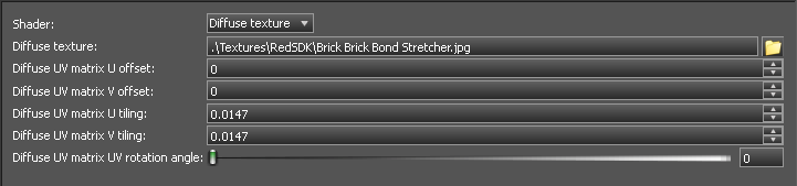
There are several parameters that control how texture maps affect a material.
Browse
The browse button opens a File Open dialog from which you can browse for a texture map file (supported file formats are JPEG, GIF, PNG, BMP).
Offset U
This offsets the texture map horizontally. Each unit of offset equals 1 Space Unit (mm, in. etc.) as specified in the Model space.
Offset by 0.5 Horizontally
 Offset V
This offsets the texture map vertically. Each unit of offset equals 1 Space Unit (mm, in. etc.) as specified in the Model space.
Offset by 0.5 Vertically.
Offset V
This offsets the texture map vertically. Each unit of offset equals 1 Space Unit (mm, in. etc.) as specified in the Model space.
Offset by 0.5 Vertically.
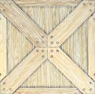
 Tiling U
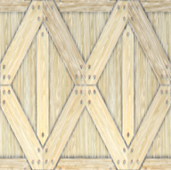
This scales the texture map horizontally. The value specifies the number of time the texture map will fit in 1 Space Unit (mm, in. etc.) as specified in the Model space. For example if the Space Unit is 1 inch, and if the scale is set to 2, the texture map will repeat 2 times within 1 inch. If the scale were changed to 0.2 it would take 5 inches to display the entire texture map.
Scaled by 2 Horizontally.
Tiling U
This scales the texture map horizontally. The value specifies the number of time the texture map will fit in 1 Space Unit (mm, in. etc.) as specified in the Model space. For example if the Space Unit is 1 inch, and if the scale is set to 2, the texture map will repeat 2 times within 1 inch. If the scale were changed to 0.2 it would take 5 inches to display the entire texture map.
Scaled by 2 Horizontally.
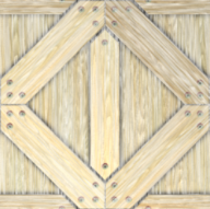
 Tiling V
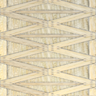
This scales the texture map vertically. The value specifies the number of time the texture map will fit in 1 Space Unit (mm, in. etc.) as specified in the Model space. For example if the Space Unit is 1 inch, and if the scale is set to 2, the texture map will repeat 2 times within 1 inch. If the scale were changed to 0.2 it would take 5 inches to display the entire texture map.
Scaled by 4 Vertically.
Tiling V
This scales the texture map vertically. The value specifies the number of time the texture map will fit in 1 Space Unit (mm, in. etc.) as specified in the Model space. For example if the Space Unit is 1 inch, and if the scale is set to 2, the texture map will repeat 2 times within 1 inch. If the scale were changed to 0.2 it would take 5 inches to display the entire texture map.
Scaled by 4 Vertically.
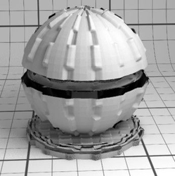
 Rotation
This Rotates the texture map by the number of degrees specified.
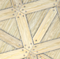
Rotated by 30 degrees
Rotation
This Rotates the texture map by the number of degrees specified.
Rotated by 30 degrees
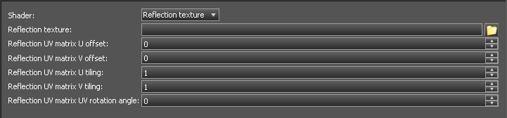
Reflectance
Reflections can be anisotropic, Fresnel-style and glossy. All those effects need dedicated parameters to be modeled.
 If set to color, that color will be the degree of reflection of the material.
 If a texture map is selected the mapped image will be used to control the reflection of the material.
 Both the color and any texture map rely on classical RGB format coding for the reflection. White (RGB 0, 0, 0) equals total reflection, and Black (RGB 256, 256, 256) equals zero reflection.
Example of an applied texture map for reflection with anisotropy
Both the color and any texture map rely on classical RGB format coding for the reflection. White (RGB 0, 0, 0) equals total reflection, and Black (RGB 256, 256, 256) equals zero reflection.
Example of an applied texture map for reflection with anisotropy
Anisotropy
The anisotropy parameter varies in [0, 1] and describes how the reflection is oriented regarding to the surface orientation. Some real-life materials are well-known anisotropic ones: CD-ROM surface or hairs and fur for example. By default, a value of 0.5 makes the material isotropic (i.e. reflections do not vary with the orientation of the surface). Make the value smaller or greater to slightly modify the way the light is reflected at the material surface.
 Click and drag the slider to change the orientation of the anisotropy.
The Samples Count changes the refinement of the anisotropy significantly.
Click and drag the slider to change the orientation of the anisotropy.
The Samples Count changes the refinement of the anisotropy significantly.
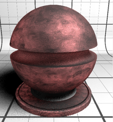
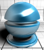
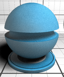
Glossiness
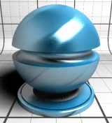
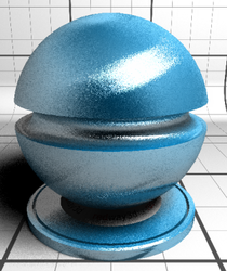
The glossiness parameter controls how much the reflections are blurry. The samples parameter controls the noise level of the glossy reflections. Differences in the Glossiness setting can be seen below. Glossiness at 0.01
 Glossiness at 0.05
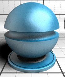
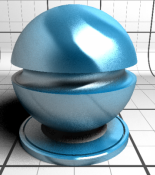
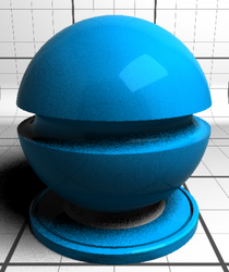
Glossiness at 0.99
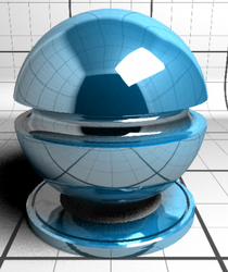
Fresnel Reflection
Fresnel support is essential as it is the way real surfaces interact with the light. The strength of the reflection generally depends on the viewing angle (the angle between the observer and the surface normal). Fresnel reflection OFF
 Fresnel reflection ON
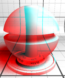
Transparency
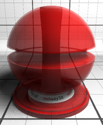
Both the color and any texture map rely on classical RGB format coding for the reflection. White (RGB 0, 0, 0) equals total transmission, and Black (RGB 256, 256, 256) equals zero transmission. Color also affects the color of light transmitted through the material. Transmission color set to grey, and the Diffusion color is set to white.
 Transmission color set to red, and the Diffusion color is set to white.
 Transmission color set to grey, and the Diffusion color is set to red
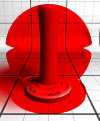
 Transmission color set to red, and the Diffusion color is set to red.
 As for the reflections, transmission can be glossy or not. Therefore, the same glossiness controlling parameters that are available for reflections are available for transmission.
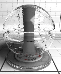
IOR (Index of Refraction)
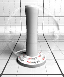
What makes the transmission effect acting like a magnifying/minifying glass is the Index of Refraction (IOR) of the material. Users can enter the value they need in the IOR field of choose one in the drop-down list (amongst various real-life material IORs). IOR set to 1.00
 IOR set to 2.00
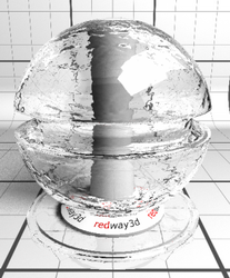 See how in the previous image, the Total Internal Reflection (TIR) increases with the increasing IOR. In jewelry, where materials have strong IORs, the TIR effect is responsible for most of the final appearance of the object and must be carefully handled.
Example of an applied texture map for transmission
See how in the previous image, the Total Internal Reflection (TIR) increases with the increasing IOR. In jewelry, where materials have strong IORs, the TIR effect is responsible for most of the final appearance of the object and must be carefully handled.
Example of an applied texture map for transmission
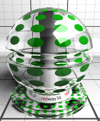
Note: IOR has zero affect when transmission uses a texture map.
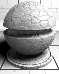
Bump Map
This category enables you to make a surface appear rough or bumpy. The rendering engine simulates shadows along the surface to create the textured effect. For example, you can define a Leather texture.
This allows you to give more details to surfaces without paying the cost of detailed modeling, users can setup their materials to use bump mapping.
The supplied texture map is automatically converted to a normal map and therefore must be given in a classical RGB format to encode the elevation. The amount of bump can be tuned through the scale factor. White (RGB 0, 0, 0) equals the highest points in the map, and while Black (RGB 256, 256, 256) equals lowest points in the map.
Displacement
This category enables you to make a surface rough or bumpy. Unlike bump maps, Displacement actually alter the geometry used to render the object.
This allows you to give more details to surfaces without paying the cost of detailed modeling, users can setup their materials to use displacement mapping, however displacement will create a greater rendering time than bump maps
displacement The supplied texture map is automatically converted to a normal map and therefore must be given in a classical RGB format to encode the elevation. The amount of bump can be tuned through the scale factor. White (RGB 0, 0, 0) equals the highest points in the map, and while Black (RGB 256, 256, 256) equals lowest points in the map.