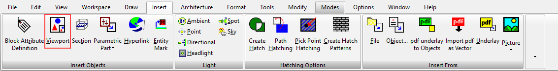
Default UI Menu: View/Viewports/Viewport
Ribbon UI Menu:
The following example will be used to demonstrate the use of viewports. To try it yourself, open the file clamp.tcw in the Samples\3D Samples folder.
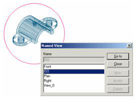
- Switch to Model Space, and select View / Named View. Several views have already been defined. (For details on named views,
- There is already one Paper Space tab, containing several viewports. Right-click on the tab and select Insert to create a clean Paper Space.
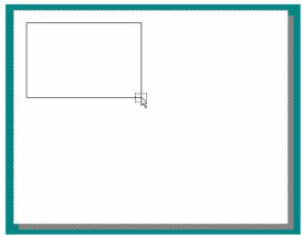
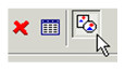
3.Select Insert / Viewport (or use the Insert Viewport icon) and define a rectangular boundary in one corner.
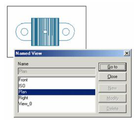
- In the Named View window, select the desired view (in this case, Plan). Clicking Go To will display the view without closing the window; this is a good way to check that the view is correct, If you double-click a named view, the view will fill the viewport and the window will close.
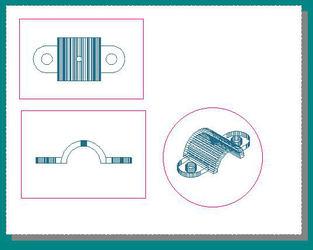
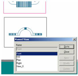
- Insert another viewport containing the Front view.
Once a viewport is created, the view inside it can be changed (as well as other parameters) by accessing its Properties.
Tip: If you want to create a viewport of the same size as an existing one, you can copy it . You can then open its Properties to select another view.
Local menu option:
Shaped Viewport: Enables you to use any closed 2D object as the viewport boundary.
- In the Paper Space drawing sheet, use the 2D tools to create the closed boundary, in this case, a circle.
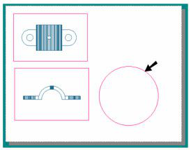
-
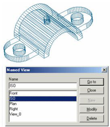
Activate Insert Viewport with the Shaped Viewport option. Select the closed boundary you just created.
-
Select a view as before, in this case, ISO.