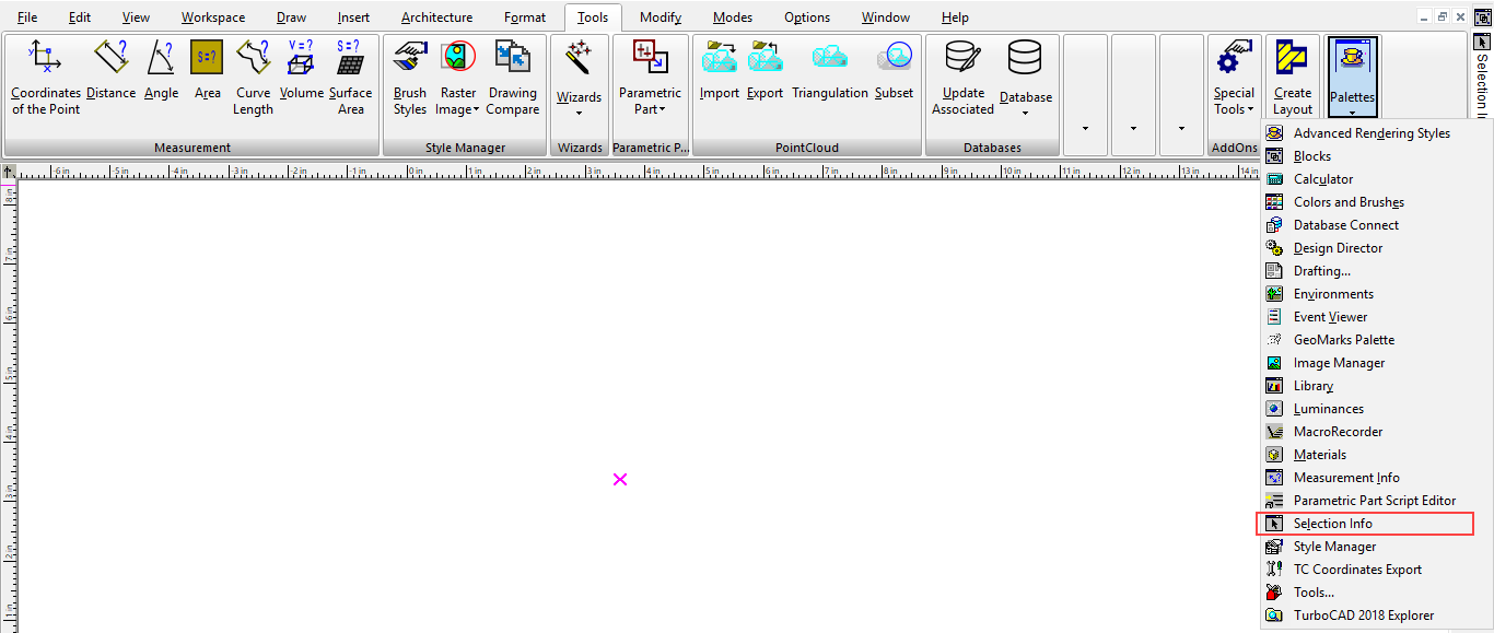
Default UI Menu: Tools/Palettes/Selection Info
Ribbon UI Menu:
Note: For details on using the Selection Info palette for 3D objects, and to see part history, see Editing 3D Objects using Selection Info.
Selection Info- Properties
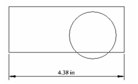
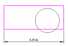
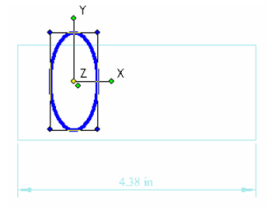
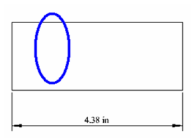
This example consists of a rectangle, a circle, and a linear dimension.
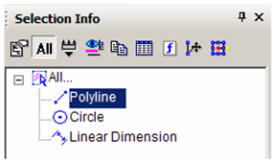
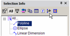
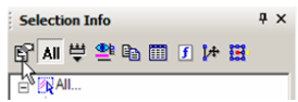
 Open the Selection Info palette to see the three objects listed.
Tip: The number of selected objects must be less than or equal to Maximum Selection Info Entities, which is set in the Program Defaults page of the TC Explorer Palette.
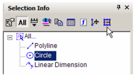
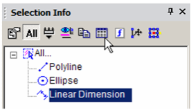
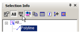
In the Selection Info toolbar, click Highlighting, and make sure Polyline is selected.
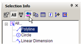
This highlights the rectangle in the drawing window.
Conversely, if you select objects in the drawing area, they will be highlighted in the Selection Info palette.
Note: If a group is selected, its objects will be listed under the group name in a similar tree format.
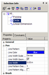
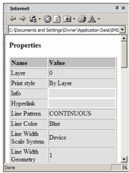
You can use this palette to change an object's properties. Highlight the circle, and the lower section of the palette contains the categories of properties for the circle. In this example, the color and line weight were changed in the Pen category.
Note: For 3D ACIS objects, physical properties are not automatically listed. Click the Physical Metrics icon in the palette toolbar if you want to see engineering properties (volume, moments of inertia, etc).
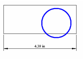
The new properties appear in the drawing area. (You may have to turn off the Highlight icon in the toolbar to see the changes.)
 To make some changes to the circle, click Select.
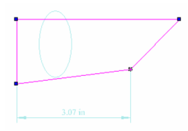
This invokes Select Edit mode, and all objects other than the circle are faded. Perform a change like moving and scaling the circle. (For details on editing this way, see Select Edit. Note that this changes "Circle" to "Ellipse" in the palette.
 Select Cancel to exit Select Edit mode.
 You can also invoke the Edit Tool. Highlight the Polyline and click Edit Tool. This enables you to reshape an object by moving its nodes.
Move one or more nodes to change the shape.
 To exit the Edit Tool, select Cancel twice.
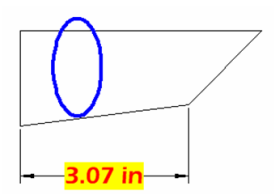
To change the dimension, highlight and make changes in the Text category.
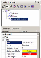
The changed dimension appears in the drawing area.
Note: You can also edit an object's properties by clicking the Properties icon in the palette toolbar. This opens the Properties window for the object see Object Properties.
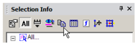
 The Copy icon is used to view an object's properties in HTML format They will appear in your default browser. The HTML file is stored in the ...Profiles/Built-in folder.
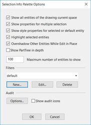
To set options for the Selection Info palette, click Options.
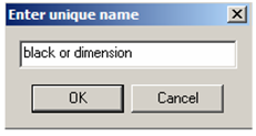
The options at the top control highlighting and fading for objects that are not being edited. To set a filter for what objects are displayed in the palette, click New. This options the Selection by Query window, in which you can specify types of objects you want to display. In this example, all objects that are either black or dimensions will be displayed in the palette.
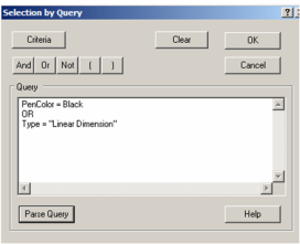
Note: For details on selecting by query, see Select by Query.
- Each filter must be assigned a name.
- To apply this filter, click Filter in the toolbar.
- Select the filter you just created.
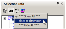
Now only the polyline and dimension appear in the palette.
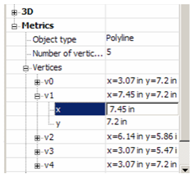
- You can change geometry by modifying geometry in the Metrics category. Open Metrics for the Polyline - the coordinates for each vertex are listed.
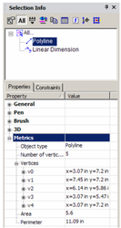
\5. Open the branch for a vertex to see its X and Y coordinates. These values can be changed.
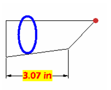
The vertex highlighted in the palette is also highlighted in the drawing area.
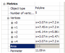
Some values cannot be edited, such as Area and Perimeter. These values depend on the coordinates of the vertices, and are grayed out
. 
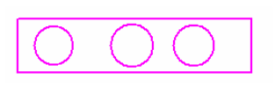
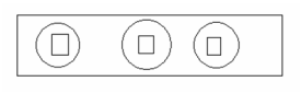
- To see options for another type of object, create several objects and group them (select them, then select Format / Create Group).
The Extents Size parameter has been added to the selection Info palette properties. Extents Size parameter also works with groups, blocks and insertions. You can use the ‘Extents size’ property to select entity according to size valuation. Select objects that you think are big or small, or object in any range you want.
The Extents Size update provides you with additional flexibility so that you can use this parameter for various needs and for analyzing wrong entities.
Demo Video:
https://youtu.be/6y4uCMfXFi0
The Extents Size update provides you with additional flexibility so that you can use this parameter for various needs and for analyzing wrong entities.

You can also select objects on the basis of extents size parameter using Select by Query see Select by Query.
Note: For details on groups, see Groups.
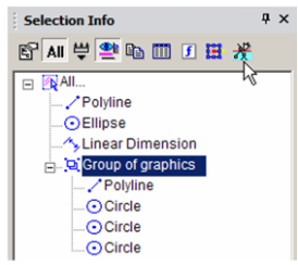
\1. This object is a "Group of Graphics," and you can open it to see each object that comprises the group. To edit the group, click Edit Content.
\2. The group's contents fill the screen. Make some change, such as adding or removing objects from it.
\3. When finished, click Finish Edit Content.
Selection Info- Constraints
The Constraints tab of the Selection Info palette shows what constraints have been applied, and to which objects they are applied.
For details on constraints, see Constraining Geometry.
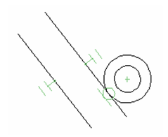
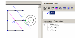
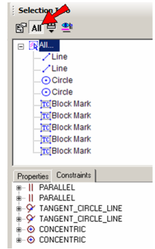
This example consists of two lines and two circles. Three constraints were applied: the two lines are constrained to be parallel, the circles are constrained to be concentric, and a tangent constraint was applied to the outer circle and adjacent line.
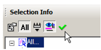
\1. Make sure the All icon is disabled at the top of the Selection Info palette. Select the outer line, which only has one constraint (parallel). In the Constraints tab, the PARALLEL constraint is listed, below which are listed the two lines to which the constraint applies.
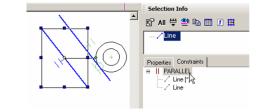
\2. Move the cursor over the PARALLEL constraint in the Constraints tab, and the two lines that have this constraint are highlighted.
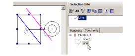
\3. Move the cursor over either line below PARALLEL. The relevant line is highlighted.
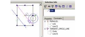
\4. Now select the inner line, which has two constraints applied to it. These two constraints are listed: PARALLEL and TANGENT.
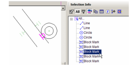
\5. Now click All. The four objects (two lines, two circles) are listed, along with several block marks. These are the constraint markers themselves, which can be selected and deleted if you want to remove the constraint. In the Constraints tab, two items are listed for each constraint - one for each of the constrained objects.
\6. Select any block mark in the palette to see it highlighted onscreen (Highlighting must be enabled).
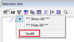
Audit System:
“Audit” is added to menu “Filters”. Audit System is used to detect a ‘bad’ object in drawing. A ‘bad’ object triggers at least one audit conditions.
font-weight: normal;
font-style: normal;">New item “Audit” was added to menu “Filters”.
- The possibility to highlight ‘bad’ objects in Selection Info palette
- The possibility to turn on/off audit conditions and changing their parameters
- The possibility to generate audit report for one or more objects
- The possibility to filter ‘bad’ objects in Selection Info palette
The possibility to send notify (about a ‘bad’ object) to Event Viewer palette
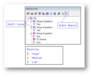
The bad objects are highlighted in the selection info palette with severity mark with audit icons.
Audit Report:
We can also generate an audit report by clicking on audit report icon on menu bar of selection info palette.
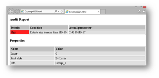
"Audit" report (HTML page).
Audit Options:
Audit icons which are shown in selection info palette with objects can be enabled or disabled by Selection Info Palette Options dialogue box. To open Selection Info Palette Options dialogue box select options icon from selection info menu bar.
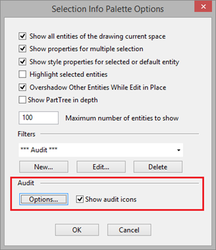
Select "Options..." from Selection Info Palette Options.
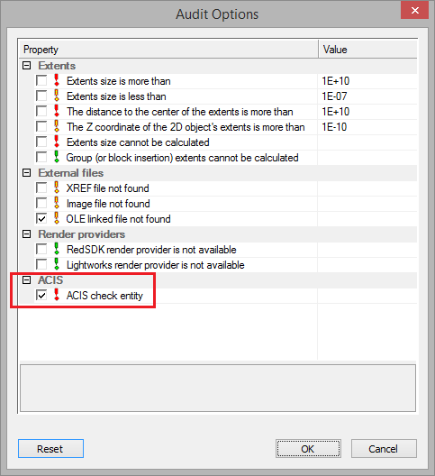
“Audit” section
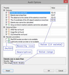
Audit condition 'ACIS check entity' (Level = 70) was added. Switched 'Off' by default.
Demo Video:
https://youtu.be/DUOAOwo0CpM