(Available in Pro Platinum)
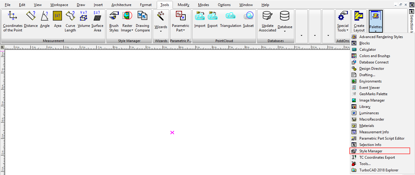
Default UI Menu: Tools/Palettes/Style Manager/Profile Styles
Ribbon UI Menu:
Profiles are used to define custom shapes for doors, and windows. Once you have created the profile, the profile is selected as part of the window or door's profile.
Note: If you want to save styles to a template,
The first example will show how to use a profile for a door shape.
Example 1- Door Profile with One Boundary
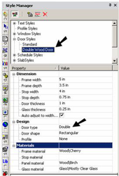
- Before creating the door, create a new door style. This one is a double door with a rectangular shape.
Note: For details on doors,
- Create walls and insert the door. Use the door's Properties window to set the overall size and elevation of the door.
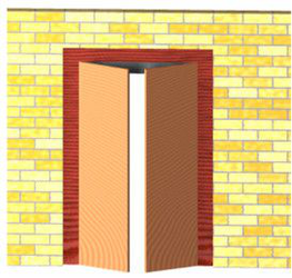
This is the door that will be modified with a profile.
- First, look at the Delay Style Modification icon; if it is enabled, you cannot create a new profile. Make sure Delay Style Modification is off.
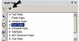
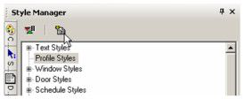
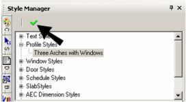
- Highlight Profile styles and click Create New Style.
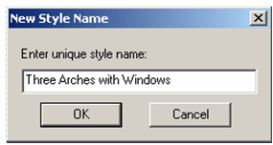
- Assign a name to the profile.
-
When you create a profile, you switch to Edit Geometry mode, and anything you have in your file is removed from view. Because you are creating a 2D profile, switch to World Plan view.
-
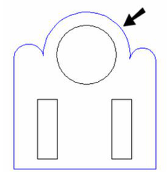
Use Polyline, Arc or Circle tools to create closed curves for boundaries and holes. In this example, the outer shape and the two rectangles were created using Polyline. The circle was created using Circle Center and Point.
You can have one or more boundaries, but boundaries cannot overlap. Holes must be entirely within a boundary.
- To define which curves will be used for boundaries, select Edit Boundary Profile.

- Click the boundary curve or curves, which turn blue when selected.
-
Select Finish from the local menu or Inspector Bar.
-
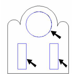
To define which curves (if any) will be used for holes, select Edit Hole Profiles.

- Click the hole curve or curves, which turn blue when selected.
-
Select Finish from the local menu or Inspector Bar.
-
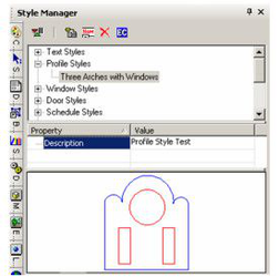
When the boundaries and holes are defined, click Finish to Edit Geometry in the Style Manager.
The profile now appears in the Preview area of the Style Manager. Boundary profiles are shown in blue, holes are shown in red.
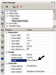
- Now return to the door profile. Under Design, set the Profile to the one you just created.
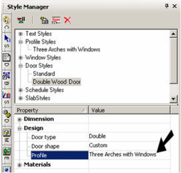
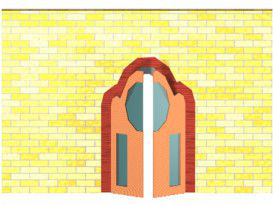
The door outline changes to match the profile. The hole profiles define the door glass, and these areas have the material specified for Glass in the door style.
- If you want to make changes to the profile, highlight it in the Style Manager, and then click Edit Content.
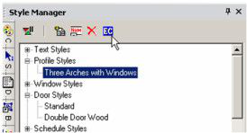
- You will return to Edit Geometry mode, where you can make your changes. When you're finished editing, click Finish to Edit Geometry. The door or window that uses the profile will update automatically.
Example 2- Window Profile with Multiple Boundaries
- In this example, create a new profile that will be used in a window.
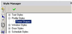
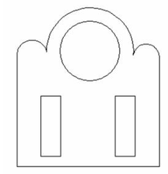
- This profile has three closed profiles, each created using Polyline.
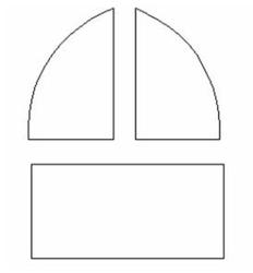
Hole profiles are not generally needed for windows, since the boundary profiles define where the window glass is. If you define holes in window profiles, holes will be placed in the glass.
- Now create a a window style that uses the profile. This example uses a Picture window.
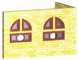
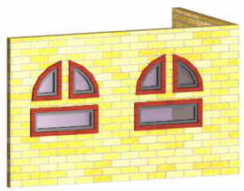
- Use the window Properties to define overall dimensions, and insert a window or two in a wall. Each window consists of three parts, defined by the boundary profiles.
- To see what hole profiles would do, use Edit Content edit the profile. Add another profile within one of the boundaries. Use Tools / Architecture / Profile / Edit Hole Profile to define the new curve as a hole. Then click Finish to Edit Geometry.
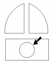
The glass now has a hole where the new profile curve was created.