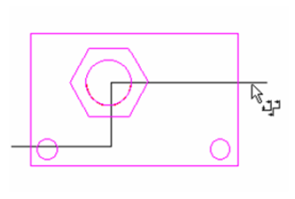
Use a Polyline to draw a multi-segmented section line on the Plan view.
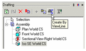
Click Create by View Line.
If you want to assign text to the view (such as a letter), enter it in the Text field of the Inspector Bar. First select the view whose sectional view you want to create.
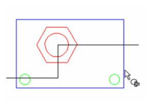
Then select the view line, in this case, the polyline.
In the next step you define the viewing direction. Move the cursor to switch between the two direction options.
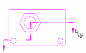
Click when the direction is correct.
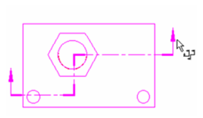
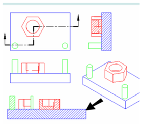
Note: You can also change the viewing direction after the section line is created. Open the section line's Properties to the Format page, and check (or uncheck) Forward Side.
The aligned view is created and is listed in the Drafting Palette, even though it does not yet appear in the drawing.
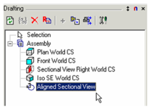
Insert the aligned view into the drawing, setting the scale according to the Plan view. By default, this is an Aligned view - what you see is equivalent to "unfolding" the polyline.
To switch to a non-aligned view, open the view's Properties to the Format page. Deselect Aligned View.
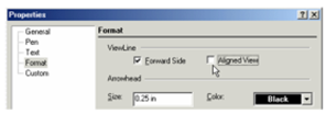 The view is no longer "unfolded."
For another way to change an aligned section view, use the Edit Tool on the polyline
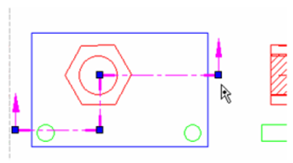
Change the polyline by moving, adding, or deleting nodes. The sectional view updates as you change the polyline.
If you want to add or change characters on the section line, use the General and Text pages of the section line's Properties.
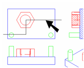
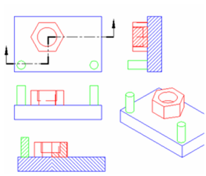
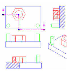
Note: that there is a difference between a section and a sectional view. The 3D function Section creates an actual section of a 3D object, whereas a sectional view is what you see when looking in the direction of the section line.
In this example, the lower view is a sectional view looking in the direction of Line A-A.
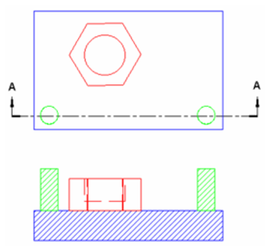 And this is the section taken at Line A-A.