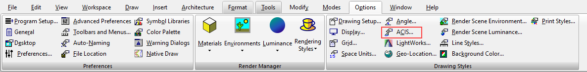
Default UI Menu: Options/Drawing Setup/ACIS
Ribbon UI Menu:
 Controls faceting of ACIS 3D solid (not surface) objects, thereby the accuracy of the model representation. Faceting generates polygonal representations of object faces, while maintaining the edge consistency between adjacent faces.
Note: The faceted representation of a face is also called a mesh.
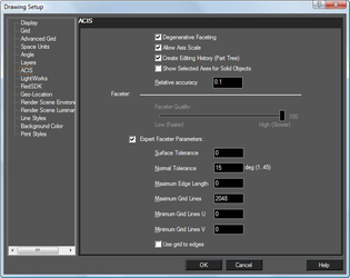
Faceting is used during rendering, and faceting refinements may have a significant impact on the rendering process. Tighter facets (higher in number) produce a smoother rendered surface, but slow down the rendering process. Degenerative Faceting: Reduces the number of edges without generating facets. Should be used if your model contains a significant number of 3D objects, because the drawing loading time will be reduced. (For files of tens of megabytes, the loading time reduction may be more than ten times.) However, rendering such a model may take much longer.
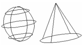
With degenerative faceting
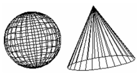
Without degenerative faceting
Note: To see the effects of degenerative faceting, check Draw form-building edges on the Display page of the Drawing Setup (Options / Display).
Allow Axis Scale: ACIS solid objects can be scaled by entering different scale values in the Inspector Bar for each axis. If not checked, scaling will be uniform, and this uniform values must be entered in the scale fields for at least two axes.
Note: This parameter is only relevant for ACIS solids. Use the Selection Info palette if you are unsure about an object's type. For example, if you create a solid box, you will need to explode it once to make it an ACIS solid.
Creating Editing History: Enables you to edit 3D objects, after they are created, in the Selection Info palette.
Show Selected Axes for Solid Objects: Applies to objects that will be assembled by axis.
Faceter
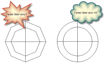
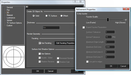
The level of facet refinement which is used to display ACIS objects can be set by the Faceter Quality slider. For greater customized control, select the Expert Faceter Parameters option, and then specify the desired values.
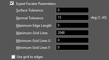
Expert Faceter Parameters
Normal Tolerance: Specifies the maximum angle (in degrees) between surface normals at points on a facet.
Surface Tolerance: Specifies the maximum allowed distance between the surface and the mesh.
Max Edge Length: Constrains the maximum length of a side of a grid cell in object space. More precisely, the maximum edge length value constrains the maximum length of a diagonal of a grid cell, because the length of a grid cell diagonal provides an upper limit for the edge length of a facet. Therefore, this parameter also constrains the maximum edge length of a facet.
Min Grid Lines U: Specifies the minimum number of u grid lines (i.e., grid lines in the u-direction).
Min Grid Lines V: Specifies the minimum number of v grid lines (i.e., grid lines in the v-direction).
Grid aspect ratio-Specifies the maximum ratio of the long side to the short side of a grid cell in 3D space. The aspect ratio value does not guarantee that triangles will have a particular aspect ratio; it applies only to the aspect ratio of grid cells. If the value of the grid aspect ratio parameter is less than or equal to 0.0, the grid aspect ratio is ignored. If the value of the grid aspect ratio parameter is greater than 0.0 and less than or equal to 1.0, a value of 1.0 is used. The default grid_aspect_ratio value is 0, which means the grid aspect ratio is ignored.
Use Grid to Edges: Specifies whether a grid is used and whether the points where the grid cuts the edge is inserted to the edge.
Object Specific Faceting
Faceting can be controlled on an individual object basis via the Properties of the object. Object specified faceting overrides the global setting in the ACIS settings.
 Two entities with new faceter options: