Symbols
A symbol is an externally linked file that is inserted in the drawing. DesignCAD provides you with a library of 2D and 3D symbols, and you
can create your own symbols by saving entities or entire drawings as a symbol.
Drawing Handles
When you save a drawing with handles, you can then load that drawing as as symbol. The handles are used to place and orient (and optionally scale) the symbol in its host drawing.
Set Drawing Handles
Menu: Point / Set Drawing Handles
Sets handles for the drawing. Use these handles to help you manipulate a drawing when you merge it with a new or existing drawing using the Load Symbol command.
Point 1: First handle
Point 2: Second handle (optional)
Point 3: Third handle (optional)
If you set fewer than three points, press Enter to end the command.
Next, choose File / Save As and rename the file or File / Save and save it with the same name. The drawing is saved with the handles in place. The next time you merge the drawing into another one using the Load Symbol command, you can position the drawing using the handles you have set.
Example: Attach a drawing of a wing to a fuselage in another drawing.
Open the drawing of the wing. Choose the Set Drawing Handles command. Set two points at the base of the wing, where it will connect to the fuselage. Press Enter.
Next, use Save As to rename the file as SETWING.DCD and click OK. When you merge the wing into the drawing of the fuselage using the Load Symbol command, you can attach the wing precisely using the handles you have set and the Gravity command.
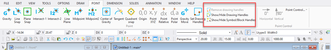
Remove Drawing Handles
Menu: Point / Remove Drawing Handles
Makes it easy to remove the existing drawing handles from the drawing. Once the drawing handles have been removed, the default handles at lower left and lower right (and top right in 3D Mode) will be used.
Show Drawing Handles
Menu: Point / Show Drawing Handles
Makes it easy to find the drawing handles for the current drawing.
Show Symbol / Block Handles Menu: Point / Show Symbol/Block Handles
Makes it easy to see the handle location for any symbols or blocks that are present in the drawing. The primary handle of each symbol will be shown as a small red dot, the secondary handle (if any) as a green dot, and the third handle as a blue dot. Note that blocks only have one handle, shown as a red dot.
Save As Symbol
Menu: File / Save as Symbol
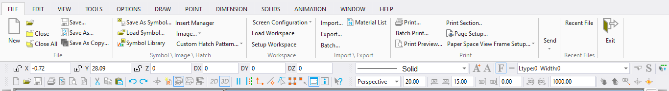
Allows you to quickly and easily save a file, or the selected part of a file, as a symbol with a separate filename.
If you want to save only selected entities, select them and choose the Save as Symbol command.
The following window appears:
Use Default Symbol Handles: If saving only the selected entities to the symbol, the selection handles will be used as the symbol handles. If the entire file is being saved as a symbol, the drawing handles will be used if there are any, or the lower left and right corners of the drawing if no handles have been set.
Set Points for the Symbol Handles: You will be prompted to set up to two points as symbol handles (up to three points in 3D mode)
Save all the entities to layer zero: All entities will be moved to Layer 0 in the symbol. This affects the way the symbol is imported into another drawing if it is exploded.
Save selected entities only: Only the selected entities will be saved to the symbol file, and the selection handles will be used as Default Symbol Handles. Otherwise, the entire file is saved, and the drawing’s handles will be used as Default Symbol Handles.
If you want to save the entire drawing as a symbol, simply choose the Save as Symbol command. DesignCAD will ask you to specify the name and DesignCAD version of the symbol file.
Load Symbol
Menu: File / Load Symbol
Shortcut Key: Ctrl+F9
Loads a drawing symbol or merges an existing drawing with the current drawing. Symbols inserted into the drawing with the Load Symbol command are defined as single entities, whether they are saved as part of the drawing or linked to the drawing. That is, the entire symbol is selected, moved, and erased as a single entity.
An important difference between blocks and symbols is that the visibility of a block’s entities depends on the visibility of each part’s host layer; therefore, a block can be drawn on different layers so only part of it is visible. The visibility of an entire symbol depends on the visibility status of the layer where the symbol is inserted.
Point 1: First handle for symbol placement
Point 2: Second symbol handle (optional)
Point 3: Third handle (optional, only used for a 3D drawing or symbol)
Choose the Load Symbol command and the Open window appears. From the file list, select the name of the symbol you want to load. Select the desired options. Then click the Open button.
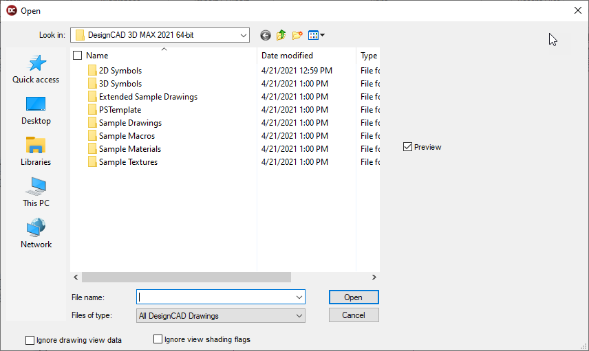
A rubber-band box appears in the drawing. This shows the area of the symbol. Set one to two points to establish the location, size, and orientation of the symbol. To accept the symbol’s size and orientation, set a point to establish the location, and then press Enter.
Load file as block: Loads a block from an external file, and adds the block definition to the list of defined blocks.
Load file reference only: The contents of the symbol is not added to the drawing’s data, but must always be loaded from the external file.
Load as original entities: Think of this as “Paste From File” or “Merge”. The entities from the selected drawing are added to the current drawing (possibly scaled and repositioned). Entities in Layer 0 of the selected drawing may be moved to the current layer, depending on the “Merge Layer 0 items onto the current layer” setting in Options/ Preferences. Entities from any other layers are placed in their original layers in the current drawing.
Load and explode: Loads the drawing as a symbol, then explodes it. The results of this option are affected by the Symbol Explode Settings in the Preferences.
Use original scale: Controls whether the loaded entities can be dynamically rescaled as they are being loaded.
Select object when created: If checked, the loaded symbol/block/entities are selected after being loaded into the current drawing.
Manipulating a Symbol
A symbol must be exploded in order to change its characteristics such as color, line style, etc. There are two ways to explode a symbol: the Load and Explode option in the Load Symbol window (before the symbol is loaded); or use Edit / Selection Edit / Convert (after the symbol is loaded).
When a referenced symbol is exploded with the Explode command, the symbol file is not read from an external file when the drawing is loaded. A copy of the drawing information for the symbol is placed into the drawing instead of an insertion entity.
When a non-referenced symbol is exploded with the Explode option or command, there is no change to the drawing unless it contains multiple copies of the same symbol. If several, non- referenced copies of a symbol exist in the same drawing, they share drawing information even though that drawing information is contained in the drawing file that contains the symbols (not an external drawing file). In order to manipulate one of the copies of the symbol, it must be exploded so that it will have its own set of drawing information.
If the Group Object when Created option in the General options is enabled, the symbol will still be recognized as a group once it has been exploded. This way it is not necessary to select many small items just to change the color, line style, etc. of the former symbol. The Group Explode command may then be used if individual items need to be manipulated.
Symbol Library
Menu: File / Symbol Library
Works like the Load Symbol command, but it brings up a window that shows small preview images, or “thumbnails,” of the symbols that are available in the different symbols libraries that come with DesignCAD.
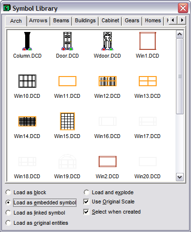
Use the scroll bar on the right side of the window to scroll through the various symbols. Click the tabs or use the scroll bar at the top of the window (just under the title bar) to switch libraries.
DesignCAD allows you to view the DesignCAD files contained in a directory and all of the DesignCAD files in one layer of subdirectories of that directory. To view a different set of symbols click on the tab with a folder symbol on it. The Path window opens. Select a new folder and click OK.
Load as Block: Loads the symbol so it will be recognized as a block. Once the symbol has been loaded as a block, additional copies can be added to the drawing using the Block Insert command. This option makes it easy to use a block/attribute definition combination that you use frequently in other drawings. Just create a drawing that contains only the block and its attribute definition. Save the drawing. Open the file in which you want to use the block. Using the Load Symbol command, load the block and attribute definition drawing you just saved, making sure that the Load as Block option is enabled.The block will still be recognized as a block.When additional copies are placed using the Block Insert command, the attribute definition will function just like it did in the original drawing.
Load as Embedded Symbol, Load as Linked Symbol: Determines whether the drawing being added or merged with the current drawing will be saved as a part of the drawing, or just linked by a reference. If the symbol is saved as part of the current drawing, the file size will be larger, and the drawing will not be updated when the symbol file is modified. The advantage is that the drawing will not be affected if the symbol file is deleted, or the drawing is opened on a computer that doesn’t have a copy of the symbol file.
If the box is checked, the program adds an “insertion entity” to the drawing file. The symbol file is read every time the drawing is loaded. The symbol file must be present and in its original location. If the symbol file is modified, the change will be reflected in all the drawings using that symbol.
Load as Original Entities: Entities are added and embedded as individual entities, not grouped as one symbol.
Load and Explode: When a referenced symbol is exploded, the symbol file is not read from disk when the drawing is loaded. A copy of the symbol is placed into the drawing instead of an insertion entity, just like a symbol that was loaded without using the Load File Reference Only option.
Select When Created: The symbol is automatically selected when it is added to the drawing.
Placing a Symbol in Your Drawing
When you find the symbol that you want to use, there are two different methods for bringing it into the drawing:
- Move the cursor over the desired symbol, press and hold the left mouse button, drag the cursor to the desired location in your drawing, position the cursor and click the mouse button to drop the symbol into the drawing
- Move the cursor over the desired symbol, double-click the left mouse button, move the cursor to the desired location in your drawing, and click the left mouse button again to drop the symbol into the drawing.
Door and Window Symbols
DesignCAD provides some standard architectural symbols for doors and windows.
Door
Menu: Draw / Door
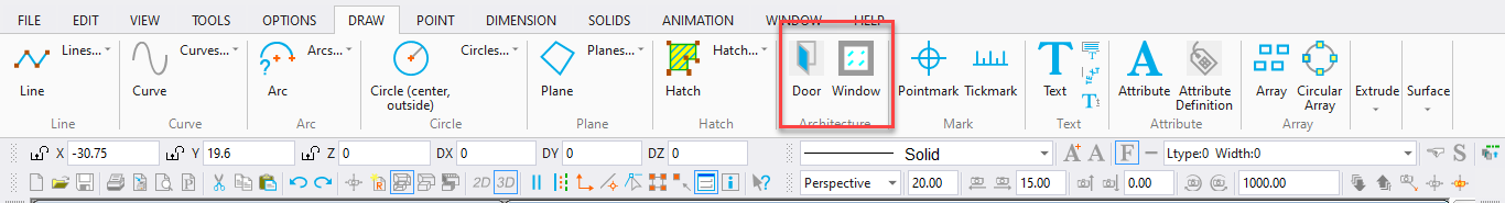
Inserts a standard architectural symbol for a door.
Point 1: Location of the center of the door or one end of the door
Point 2: Orientation of the door
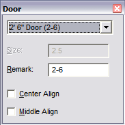
Select the desired door size and type from the list box. If you choose Custom Door or Custom Sliding Door, specify the size in the Size box.
By default, the door size appears in the Remark box unless Custom is selected. However, any information can be entered in the Remark box to be inserted into the drawing with the door. Check the Center Align box to align the door by the center or uncheck it to align the door by one end. Check the Middle Align box to align the door in the middle of a double line.
Set the first point for the door. A rubber-band door appears, showing how the door would look with the second point set at the current cursor location. When the door is positioned to your liking, set the second point. The Line or Double Line into which the door is placed will automatically be cut and capped.
Window
Menu: Draw / Window
Inserts a standard architectural symbol for a window.
Point 1: Location of the center of the window or one end of the window
Point 2: Placement of dimension text and orientation of the window, if necessary
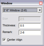
Select the desired window size, or Custom, from the list box. If you choose the Custom option, enter the size in the Size box. By default, the window size appears in the Remark box unless Custom is selected. However, any information can be entered in the Remark box to be inserted into the drawing with the window. The Thick- ness is 0.50 by default. Change the Thickness if desired. Check the Center Align box to align the window by the center or uncheck it to align the window by one end.
Set the first point for the window. A rubber-band window appears. A rubber-band window appears, showing how the window would look with the second point set at the current cursor location.
When the window is positioned to your liking, set the second point. The Line or Double Line into which the window is placed will automatically be cut and capped