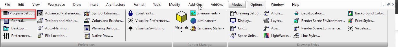
Program Setup
Program Setup
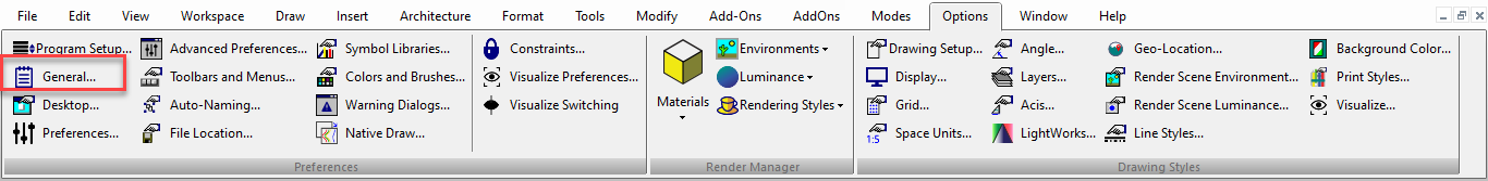
Default UI Menu: Options/Program Setup
Ribbon UI Menu: 
Contains pages in which you can control TurboCAD program settings. You can access each page directly from the Options menu. The options that you set in this window are saved when you exit TurboCAD and will remain in effect the next time you start the program. The Program Setup pages can be accessed from the Options menu.
You can also display the Program Setup toolbar by right-clicking in any toolbar area and selecting Program Setup.
Tip: You can also use the System Defaults in the TC Explorer Palette to set program setup options
Program Setup dialog box has an ability to search via search bar available. It is easy to locate the settings in the complete dialog sub-options.
Auto-Naming
Default UI Menu: Options/Program Setup/Auto-Naming
Ribbon UI Menu:

Controls how groups, blocks, and symbols are named. 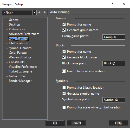
Prompt for name: You will receive a prompt each time a new item is created. Generate names: Names will be automatically assigned. Prefix: If names are automatically generated, you can enter a string that appears before the item name. The "@" character is a placeholder for the automatic number. Insert blocks when creating: Each block will be inserted into the drawing once it is created. Prompt for library location: If not checked, all saved symbols will be stored in the default folder.
Note: If you turn off both the Prompt for name and Generate names options, names will not be assigned to groups.However,names will be assigned to blocks and symbols.
Color Palette
Default UI Menu: Options/Program Setup/Color Palette
Ribbon UI Menu:
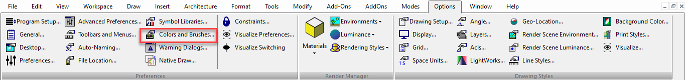
Enables you to add, modify, or delete colors from the TurboCAD palette. 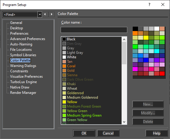
To add a new color, type the name and click New. You will then be prompted to select a color from the color wheel. You can modify a color by selecting it from the list and clicking Modify. Delete a color by selecting it and clicking Delete. When you have the colors you want, they can be displayed for easy selection in the Colors and Brushes palette.
The Color Wheel
You can set colors by RGB values, or by Hue, Saturation, and Value numbers. Red, Green, Blue: Sets the amount of each color in the light. Values can be a maximum of 255. Hue: The color value, where 0 is red, 60 is yellow, 120 is green, 180 is cyan, 200 is magenta, and 240 is blue. If you change the hue, the values for red, green, and blue will be changed to match. Sat: The saturation level for the color (amount of color), up to a maximum of 240. Lum: The luminosity (brightness) of the color.
Constraints
Default UI Menu: Options/Program Setup/Constraints
Ribbon UI Menu:
Settings and controls for geometric and dimensional constraints. 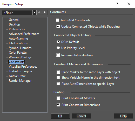
Auto Add Constraints: If checked, the Auto Add Constraints tool is enabled. Any constrainable geometry you create while this is active will have constraint automatically assigned. Update Connected Objects while Dragging: Dynamically updates the position, shape, and size of constrained objects as you drag them within the Edit tool. Connected Objects Editing: DCM Default: Changes to any part of a set of constrained objects can affect all objects equally. Use Priority Level: Constraint changes to any part of a set of objects will affect that part first, with minimal changes to the remaining objects. Incremental Evaluation: Constraint changes are constantly checked and changes are being made. If disabled, the results will be checked only after changes are made. For large scale changes, this option should be enabled.
Constraint Markers and Dimensions
Place marker to the same layer with object: Constraint markers are placed on the same layer as the object that is constrained. Otherwise, they are placed on their own layer. Show variable name in dimension text: Displays the variable name in parentheses after the dimension value. Printing: Choose whether constraint markers and constrained dimensions will be included when printing.
Desktop
Default UI Menu: Options/Program Setup/Desktop
Ribbon UI Menu:
Controls what appears on the screen.
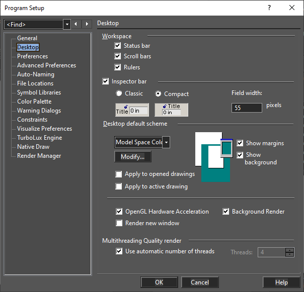
Workspace: Controls the display of the working area Status Bar: Displays or hides the Status Bar. Scroll bars: Displays or hides the scroll bars. Rulers: Displays or hides the rulers.
Inspector Bar
Inspector Bar: Displays or hides the Inspector Bar. Classic: Set Inspector bar fields and labels to be in the classic side by side orientation, Compact: Set Inspector bar fields and labels to be in the compact over/under orientation, Field width: Specify the field width.
Desktop default scheme
Desktop Scheme: Customizes the color of paper and background, and floating palettes. Click Modify to change an element's color.
Tip: You can also click the different elements in the preview window.
Show margins: Displays page (printer) margins. Show background: If checked, the background behind the paper will be displayed. If unchecked, the background will be white. Apply to opened drawings: Apply changes in the scheme to all opened drawings. Apply to active drawing: Apply changes to the currently active drawing.
Tip: You can switch off the paper until you're ready to print, then use the Page Setup to place your drawing on the page.
OpenGL Hardware Acceleration: Available if your video card is equipped with an accelerator, take this characteristic into account while performing a render. Render new window: When you render your drawing, the render view will open in a new drawing window. Background Render: With this option, TurboCAD tools work faster in Render mode; rendering will "interfere" less with other tools. This setting can only be applied when working with one window.
Multithreading Quality Render
Use automatic number of threads: If checked the system automatically use the full number of available threads. Threads: Specify the number of threads to be used for rendering if Use automatic number of threads is off. Multithreading LightWorks: If checked multithreading will be used for LightWorks if the plug-in is installed.
Visualize Preferences
(Available in Platinum, Professional, and Deluxe)
Default UI Menu: Options/Program Setup/Visualize Preferences
Ribbon UI Menu:
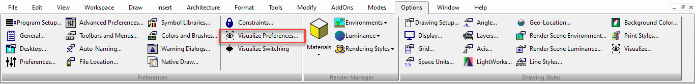
Enables you to set visualize preferences.
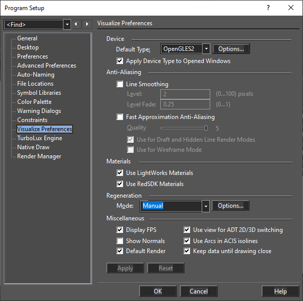
Device Type:
Device mode can be selected out of: OpenGLES2, GDI, and OpenGL.
OpenGLES2 is most advanced and most productive device mode. OpenGL, GDI device modes can be used for virtual machines and low (embedded) video cards.
Device Options:
The Device Options dialog allows you to setup Visualize device options.
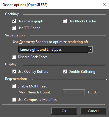
Caching:
Use scene graph
Enables usage of the optimized Scene Graphics Manager, which is an additional render layer that builds its own internal hierarchy of scene graphic objects and optimizes them in the background of multiple threads to provide better rendering performance. This option can increase memory usage up to two times but rendering performance increases up to 10-30 times.
By default: On
Enabled: If Device Type is OpenGLES2
Use Blocks Cache
Enables caching of a hierarchical block structure.
By default: Off
Enabled: Always
Use TTF Cache
Enables usage of the TrueType font cache. It is useful for rendering drawings that contain a lot of text. If TrueType font cache is enabled, each font character used inside the drawing is cached as a separate metafile.
By default: Off
Enabled: Always
Visualization:
Use Geometry Shaders to optimize rendering of
Sets bit flags that instruct the vectorization device to use Geometry Shaders (if this feature is available for the GPU) to optimize rendering performance for specific geometry features. Values:
• None: Geometry Shader is not used.
• Lineweights: The renderer invokes Geometry Shader to optimize rendering of lineweights.
• Linetypes: The renderer invokes Geometry Shader to optimize rendering of linetypes (includes plot style related linetypes and highlighting by dashed patterns).
• Lineweights and Linetypes: The renderer invokes Geometry Shader to optimize rendering of lineweights and linetypes.
Range: [None, Lineweights, Linetypes, Lineweights and Linetypes]
By default: Lineweights and Linetypes
Enabled: If Device Type is OpenGLES2
Discard Back Faces
Description: Enables back-face culling.
By default: Off
Enabled: If Device Type is OpenGLES2, and OpenGL
Display:
Use Overlay Buffers
Enables the usage of overlay buffers during rendering processes.
By default: On
Enabled: If Device Type is OpenGLES2
Double Buffering
Enables an additional intermediate off-screen buffer to avoid a blinking effect during on-screen rendering.
By default: On
Enabled: Always
Regeneration:
Enable Multithread
Enables multithreading.
By default: Off
Enabled: Always
Anti-Aliasing:
Visualize supports two types of Anti-Aliasing: Line Smoothing and Fast Approximation Anti-Aliasing (FXAA) Anti-Aliasing is available for device type OpenGLES2.
Materials:
ODA Visualize SDK render does not yet have its own materials in TurboCAD as Lightwork or RedSDK.
The structure of ODA materials is very similar to the materials of other render engines, therefore added the ability to import materials from Lightwork or RedSDK. Currently ODA render supports color, texture, transparency map, bump map, these parameters can be imported from Lightwork or RedSDK materials.
If the options 'Lightwork' and 'RedSDK' (from Program Setup\ODA Visualize page) are not set, then the default material (with graphic's color) will be used. If the options are set, then the material that has the texture will be used.
Note: RedSDK materials can be used even if the plugin is not installed, but editing of these materials is available only if the Native Draw mode is RedSDK.
Regeneration:
When changing the view (zoom, rotation), primitives can change automatically or by pressing a key F5 (Menu View\Redraw or View\Regen) Drawing speed may slow down when auto-regenerate is enabled.
The user can specify which types of primitives will be updated automatically when the view changes.
Regeneration Options:
The dialog allows you to setup regeneration options.
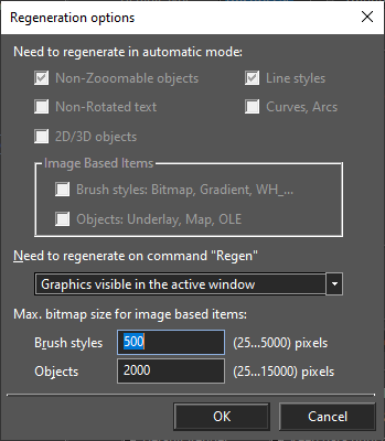
Non-Zooomable objects
Non-zooomable objects (camera, light, blockmark, unscaled text) keep their size when zooming.
By default: On
Enabled: Always
Non-Rotated text
Non-Rotated text objects keep their orientation automatically.
By default: Off
Enabled: Always
2D/3D objects
Turn on/off automatic regeneration of 2D/3D object (ADT objects, Landscapes) switching when changing camera orientation.
By default: Off
Enabled: Always
Line styles
Objects with some line styles will be updated automatically (as in GDI mode when zooming and camera rotating).
By default: On
Enabled: Always
Curves, Arcs
Curves and arcs keeps their smoothness when zooming.
By default: Off
Enabled: If Device Type is OpenGLES2 or OpenGL
Miscellaneous:
Display FPS: If this option is on, a display appears in the upper right corner of the drawing space. This display track the Frame Per Second to indicate the speed of the Visualize drawing engine and Device Type.
Show Normals: The visualization of the normals make it easier to estimate the smoothness and orientation of the 3D objects, and to find artifacts/defects on those objects. Supported in Hidden Line and Draft renderings. This option is Off by default.
Default Render: Enables usage of Visualize rendering modes by default in Draft and Hidden Line renders. This option allows the user to switch on Visualize Draft and Hidden Line render in one click.
Keep data until drawing close: Keep the Visualize contents in cache to optimize switching between paper/model spaces and Visualize/non – Visualize rendering modes.
By default: On.
Use Arcs in ACIS isolines: Enables usage arcs in ACIS isolines instead of polylines.
By default: On.
This option allows user to draw contours in the same way as GDI, and use arches to get an accurate representation of the contours.
Use view for ADT 2D/3D switching:
This option allows user to draw object 2D/3D in the same way as GDI (options is off), and draw object 2D/3D the same as in ACAD (options is on).
If the options is on switching to object 3D state occurs if the view differs from the plan view, and in this case, the orientation of the object is not taken into account
By default: On.
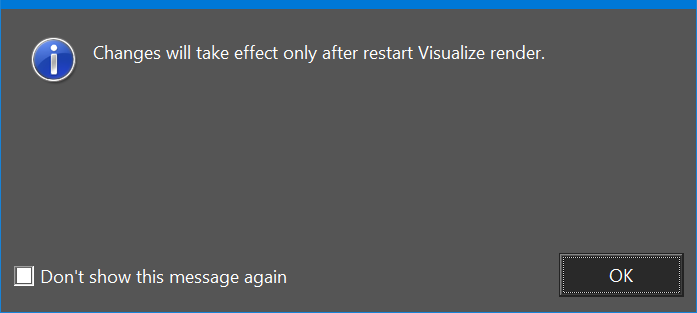
Changing this option requires reloading the Visualize render, so the corresponding warning dialog is shown.
Visualize Switching
(Available in Platinum, Professional, and Deluxe)
Default UI Menu: Options/Program Setup/Visualize Switching
Ribbon UI Menu:
Enabled in model space if camera wireframe mode is set.
The command turns on / off Visualize camera mode in wireframe
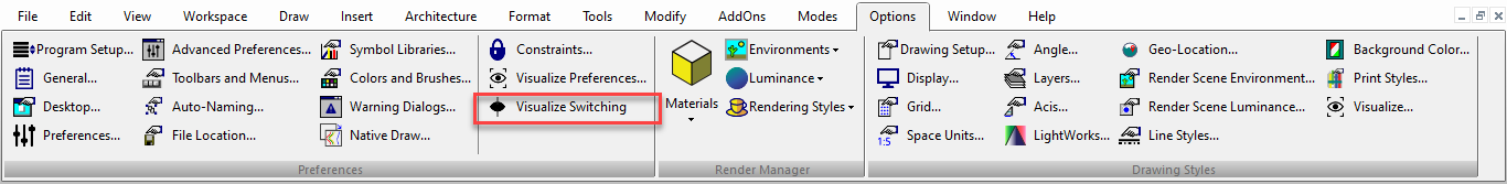
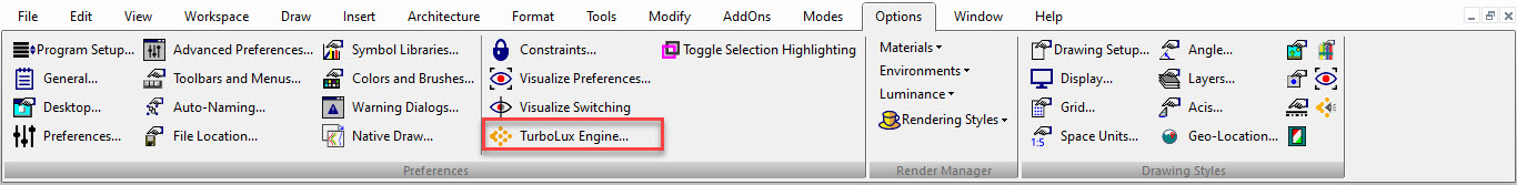
TurboLux Engine
(Available in Platinum, Professional, and Deluxe)

Default UI Menu: Options/Program Setup/TurboLux Engine
Ribbon UI Menu:
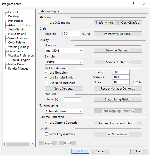
Platform
- Button Platform info...
- Button OpenCL info...
Draft
- Option Interactivity Options...
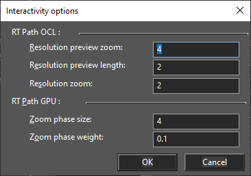
The dialog allows you to optimize draft rendering.
- 'RT Path OCL'
Resolution preview zoom Description: Render a sample every n x n pixels in the first passes. For instance 4x4 than 2x2 and then always 1x1 Recommended Range: [1 – 32] By default: 4
Resolution preview step Description: Each preview step is rendered for n frames Recommended Range: [1 – 32] By default: 2
Resolution zoom Description: Render a sample every n x n pixels, outside the preview phase, in order to reduce the per frame rendering time Recommended Range: [1 – 32] By default: 2
- 'RT Path CPU'
Zoom phase size Description: render scaled down film for the first few frames after a scene edit (to make interactions more fluid) Recommended Range: [1 – 32] By default: 4
Zoom phase weight Description: TODO (description not provided by the LuxCore render developer) By default: 0.1
Quality
Denoiser
- Option Denoiser Options...
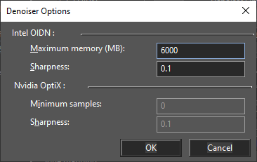
Interactivity Options The dialog allows you to set options for each denoiser type.
- 'Intel OIDN'
Maximum memory (MB) Description: Approximate maximum amount of memory to use in megabytes (actual memory usage may be higher). Limiting memory usage may cause slower denoising due to internally splitting the image into overlapping tiles. By default: 6000 Enabled: if Denoiser = Intel OIDN
Sharpness Description: Linear interpolation between the denoised result (0.0) and the noisy input (1.0). By default: 0.1 Enabled: if Denoiser = Intel OIDN
- 'Nvidia OptiX'
Minimum samples Description: Minimum amount of samples to be rendered before the denoiser is run (at lower sample numbers, it does not modify the input). By default: 0 Enabled: if Denoiser = NVidia OptiX
Sharpness Description: Linear interpolation between the denoised result (0.0) and the noisy input (1.0). By default: 0.1 Enabled: if Denoiser = NVidia OptiX
Sampler
-
Option Sampler Options...
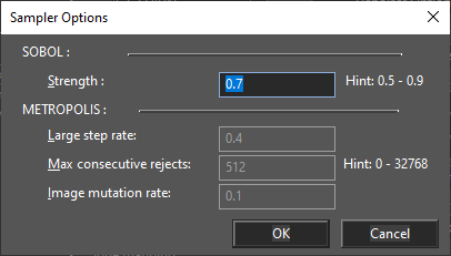
The dialog allows you to set options for each sampler type.
- 'SOBOL'
Strength Description: it sets if the sampler should be more or less adaptive. By default: 0.7 Range: [0 ≤ x < 0.95] Hint: [0.5 - 0.9] Enabled: if Sampler = SOBOL
- 'METROPOLIS'
Large step rate Description: Probability of generating a large sample mutation By default: 0.4 Range: [0 ≤ x ≤ 1] Hint: [0 - 1] Enabled: if Sampler = METROPOLIS
Max consecutive rejects Description: Number of consecutive rejects before a next mutation is forced. Low values can cause bias By default: 512 Range: [x ≥ 0] Hint: [0 - 32768] Enabled: if Sampler = METROPOLIS
Image mutation rate Description: Maximum distance over the image plane for a small mutation By default: 0.1 Range: [0 ≤ x ≤ 1] Hint: [0 - 1] Enabled: if Sampler = METROPOLIS
Halt Conditions
- Option Noise Options...
Noise Threshold Options
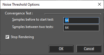
The dialog allows you to set additional Noise Threshold options.
Samples before to start test Description: number of average samples per pixel before to start the convergence test. By default: 64 Enabled: Always
Samples between two tests Description: number of average samples per pixel between two tests By default: 64 Enabled: Always
Stop Rendering Description: Set this to ‘off’ if you only want to use the halt noise threshold settings for adaptive sampling in an endless render By default: ‘on’ Enabled: Always
- Option Render Manager Options The dialog allows you to set halt conditions for Render Manager..
Time (s) Description: number of seconds before stopping the rendering in Render Manager. By default: 10 Enabled: Always
Status Bar
- Button Status String Fields...
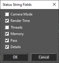
The dialog allows you to select status string fields.
Status string with all fields
Camera Mode Description: Show camera mode. By default: ‘off’ Enabled: Always
Render Time Description: Show rendering time. By default: ‘on’ Enabled: Always Threads Description: Show threads count. By default: ‘off’ Enabled: Always
Memory Description: Show used memory size. By default: ‘on’ Enabled: Always
Pass Description: Show passes count. By default: ‘on’ Enabled: Always
Details Description: Show additional fields (fields in square brackets). By default: ‘on’ Enabled: Always
Tone mapping
- Option Tone mapping Options...
Tone mapping Options The dialog allows you to set options for the tone mapping types.
-
Section 'Linear' Scale Description: tone mapping scale. By default: 1 Enabled: if Tone mapping = Linear
-
Section 'Lux Linear' Sensitivity Description: ISO sensitivity. By default: 100 Enabled: if Tone mapping = Lux Linear
Exposure time Description: exposure time. By default: 0.001 Enabled: if Tone mapping = Lux Linear
f/aperture Description: f/aperture. By default: 2.8 Enabled: if Tone mapping = Lux Linear
- Section 'Reinhard' Prescale Description: reinhard prescale. By default: 1.0 Enabled: if Tone mapping = Reinhard
Postscale Description: reinhard pstscale. By default: 1.2 Enabled: if Tone mapping = Reinhard
Burn Description: reinhard burn. By default: 3.75 Enabled: if Tone mapping = Reinhard
Gamma Correction
- Option Gamma Correction Options…
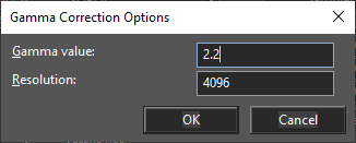
Tone mapping Options The dialog allows you to set options for the tone mapping types.
-
Section 'Linear' Scale Description: tone mapping scale. By default: 1 Enabled: if Tone mapping = Linear
-
Section 'Lux Linear' Sensitivity Description: ISO sensitivity. By default: 100 Enabled: if Tone mapping = Lux Linear
Exposure time Description: exposure time. By default: 0.001 Enabled: if Tone mapping = Lux Linear
f/aperture Description: f/aperture. By default: 2.8 Enabled: if Tone mapping = Lux Linear
- Section 'Reinhard' Prescale Description: reinhard prescale. By default: 1.0 Enabled: if Tone mapping = Reinhard
Postscale Description: reinhard pstscale. By default: 1.2 Enabled: if Tone mapping = Reinhard
Burn Description: reinhard burn. By default: 3.75 Enabled: if Tone mapping = Reinhard
#### Logging
-
Button Log Subsystems…
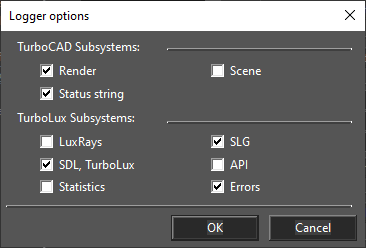
Log Subsystems The dialog allow you to enable/disable log messages of a single subsystem
- Section 'TurboCAD Subsystems'
Render Description: enable/disable log messages of a TurboCAD render By default: ‘on’
Scene Description: enable/disable log messages of a TurboCAD render scene By default: ‘on’
Status string Description: enable/disable log messages of a TurboCAD render status string By default: ‘off’
- Section 'TurboLux Subsystems'
LuxRays Description: enable/disable log messages of LuxRays subsystem By default: ‘off’
SDL, TurboLux Description: enable/disable log messages of SDL, LuxCore subsystems By default: ‘on’
Statistics Description: enable/disable log messages of LuxCore Statistics subsystems By default: ‘off’
SLG Description: enable/disable log messages of LuxCore SLG subsystems By default: ‘on’
API Description: enable/disable log messages of LuxCore API subsystems By default: ‘off’
Errors Description: enable/disable log messages of LuxCore Errors By default: ‘on’
File Locations
Default UI Menu: Options/Program Setup/File Locations
Ribbon UI Menu:
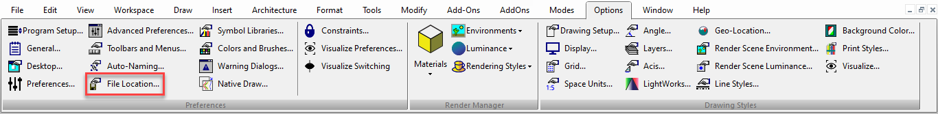
Enables you to specify the folders where TurboCAD places several types of program files. 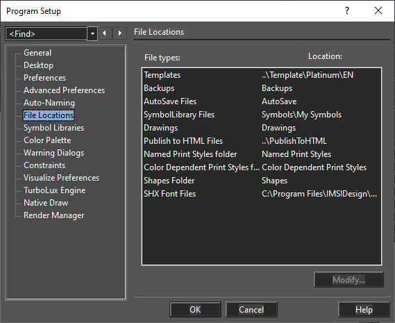
Templates (.tct) - Files in which you save settings as well as block libraries, symbol libraries, and scripts, that you can use to start a new drawing. Backups (.bak) - Backups that are created if you check Make Backup Copies option in the General page. AutoSave Files (.asv) - Files that are saved automatically, if this option is turned on in the General page. These files allow you to restore work after a system crash. Symbol Library Files (.slw) - Sets of related symbols, saved to one common .slw file or a set of drawing files saved to a specified folder. Drawings (.tcw) - Drawings and models you create in TurboCAD. Publish to HTML Files - Files created using File / Publish to HTML. Print Styles: Shapes (.shx): Shape files (.shx) used in the creating of line styles. (This is not the same as *.shx font files.)
Tip: If you have two disk drives (or access to a network drive), it is wise to have your backup files automatically saved to a second drive.
General Setup
Default UI Menu: Options/Program Setup/General
Ribbon UI Menu:
Sets file opening and saving parameters, as well as user information
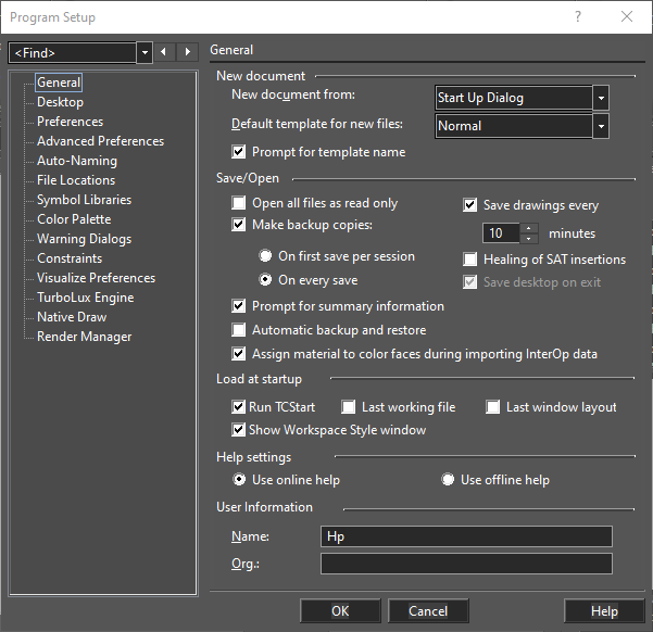
New document from: Select how files will be opened when using File / New. Default template for new files: If no template is specified when creating a file, a default template will be used. This option sets the default template. Prompt for template name: You will be prompted for a template each time you start a new file. If you want to use the default template without being prompted, clear this box. Open all files as read-only: If checked, files cannot be edited. Make backup copies: If checked, select On First Save or On Every Save to determine how often backups will be made. Backup files have the extension .bak. By default, backup files are saved in the same folder as your primary drawing files, but you can change this on the File Locations page. Save drawings every: If checked, autosave copies (.asv files) will be made at the specified intervals. After a system crash, TurboCAD will open the autosave version of your drawing as soon as you launch TurboCAD. Autosave files are stored in the AutoSave folder by default, but you can change this on the File Locations page. Prompt for summary information: The Summary Information window enables you to record user information connected to your drawing. If checked, this window will be displayed the first time that you save any drawing to disk, and whenever you use Save As to save a new copy of the file.
Automatic Backup and Restore: Backups the file and restores is automaticaaly after a specififc time interval.
Assign material to color faces during importing interOp data: (Available in Platinum only) If checked, when reading ACIS objects (SAT/IGES/STEP/SAB import), if ACIS object has colored faces, then the appropriate material is assigned to these faces.
Healing of SAT insertions: For imported files, heals gaps between faces and holes within faces.
Save desktop on exit: If checked, the desktop settings (toolbars, etc.) will be saved when you exit the program. Load at startup: You can choose to load the last working file and the last window layout each time you start TurboCAD. Help Settings: Specifies how help will be accessed. User Information: Basic user information
Preferences
Default UI Menu: Options/Program Setup/Preferences
Ribbon UI Menu:
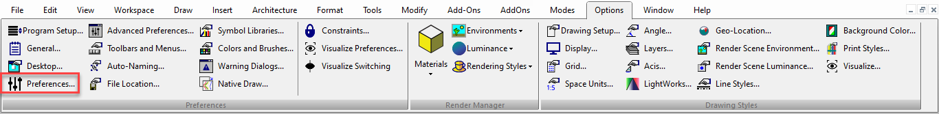
General program options, such as cursor shape, axis color, zoom factor, and display of coordinate system icons.
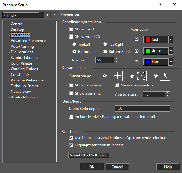
Coordinate system icon:
You can choose to display the User CS and/or World CS symbol/s.
For both, you can set the color of the axes and size of the icon.
For the World CS, select the corner of the screen where it will be displayed: TopLeft, TopRight, BottomLeft, BottomRight
Drawing cursor
Cursor Shape: Select one of the three shapes provided.
Show crosshairs: Overrides the normal cursor, displaying a screenwide horizontal and vertical line intersecting at the cursor position.
Show Isometric: Overrides the normal cursor, displaying all three axes.
Show Snap Aperture: Displays a circular area around the cursor whose radius is the Aperture Size. Aperture is used while snapping, to detect objects.
Aperture size: Specify the radius of the aperture in pixels.
You can also use the View | Display | Cursor menu to change the cursor display.
Undo/Redo
Undo/Redo depth: Sets the number of operations stored in the Undo buffer.
Include Model / Paper space switch in Undo buffer: If checked, switching between Model and Paper spaces will be included in the Undo buffer.
Selection
Use Choice if several entities in aperture while selection: If more than one object lies within the aperture area during a selection, a small window appears from which you can select the desired object.
Highlight Selection in Renders: This option allows user to disable drawing of the selected objects in all camera modes, except GDI modes (Wireframe\Native Wireframe and Hidden Line\Hidden Line). Enabling this option can cut down on render time and allow for more accurate selection of objects to be rendered.
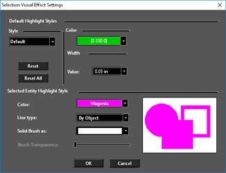
Visual Effect Settings: Settings for the various "highlighting" methods. See Selection Visual Effects Settings.
Toggle Selection Highlighting
Default UI Menu: Options/Program Setup/Toggle Selection Highlighting
Ribbon UI Menu:
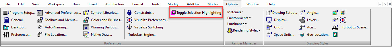
It’s a toggle option which that turns on/off "Highlight selection in renders" option in Preferences menu. This option is a convenient and the fastest way to turn on/off Selection Highlighting Option available in Program Setup/Preferences dialog box.
Symbol Libraries
Default UI Menu: Options/Program Setup/Symbol Libraries
Ribbon UI Menu:
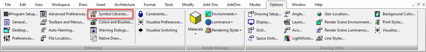
Displays the folders containing files that can be viewed in the Library palette. 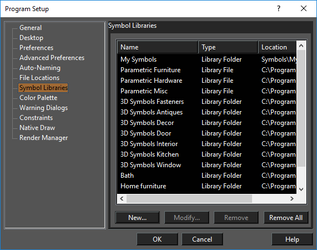
Click New to add more folders. You can also modify the name of a library folder or file, or delete or modify symbol library files and/or folders. You can also access the symbol libraries from the Library palette.
Toolbars and Menu
Default UI Menu: Options/Toolbars and Menus
Ribbon UI Menu:
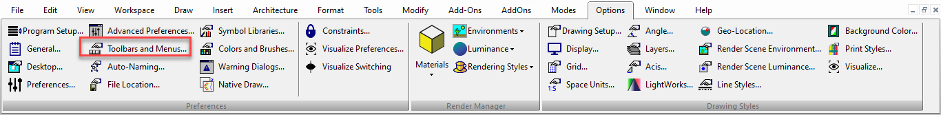
Open the Customize window to the Toolbars page to modify toolbars.
Warning Dialogs
Default UI Menu: Options/Program Setup/Warning Dialogs
Ribbon UI Menu:
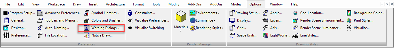
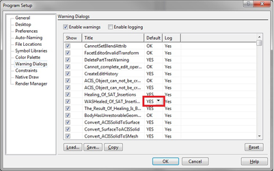
Controls the display of TurboCAD warning messages. If you received a warning message with the "Don't show this message again" checkbox, the warning message will appear in this table. Use the Show column to show or hide messages.UI enhancements of the Warning dialogs page Show/hide list columns. Right click on the header of the list to open the local menu. This makes it possible to show/hide list columns. NOTE: The first three columns are always visible.
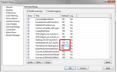
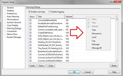 Setting the value in the 'Default' and 'Log' columns Left clicking in a cell in the 'Default' or 'Log' column will cause a drop-down, combo box to appear, thereby allowing you to change the setting of that cell.
. 
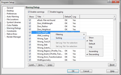
 Sorting Columns in the appropriate order Columns can be sorted in two ways:
- Via left click at the header of the appropriate column
- Via local menu command. This local menu can be called via a right click within the list.
For the Time Column, the default sets the time in ascending order.
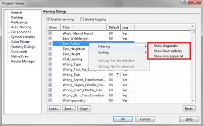
 Filtering the contents of the list The ability to filter the contents of the list is available via the local menu. This local menu can be called via a right click within the list The filtering commands are:
- Show diagnostic - in addition to displaying normal content, the list also shows diagnostic messages. FALSE by default.
- Show fixed visibility - in addition to the normal content of the list also show messages for which the 'Show' state cannot be changed. FALSE by default.
- Show only appeared - Show only those warnings which have already appeared. If this option TRUE the content of the list is equal to the contents of this list in the all previous TurboCAD versions. TRUE by default.
 Changing Multiple 'Log' or "show' Settings Since the cells in the 'Log' column can have only two values ('Yes' and 'No'), it is convenient to change the value for the multiple selected cells (it is also possible to do this with the 'Show' column). This is possible through the local menu. For Log: Simply use Click and SHIFT to select the cells, then open the local menu and select the appropriate yes or no option. For Show Simply use Click and SHIFT to select the cells, check or uncheck the option box.
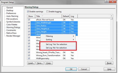
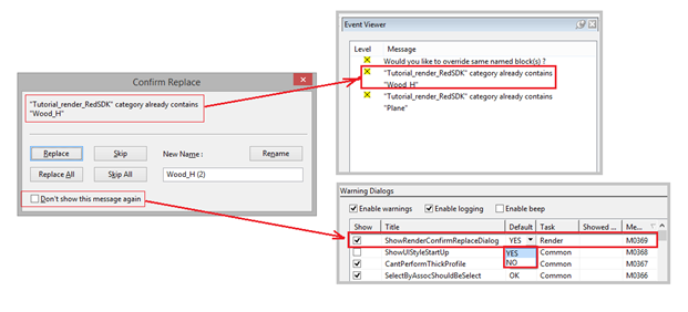
Confirm replace Warning Message
*TurboCAD (Platinum, Professional, and Deluxe)*
Now, if you tick the checkbox program will remember the last selected option and will not show the dialog again.
This dialog could be enabled again through Warning dialogs in Options.
Native Draw
Default UI Menu: Options/Program Setup/Native Draw
Ribbon UI Menu:
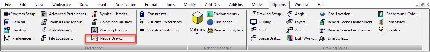
The Native Draw dialog allows you to specify which display/drawing engine will be used. you can select between standard GDI and Redsdk. GDI uses standard Windows CPU based drawing technology and CPU based OpenGL hardware acceleration. Redsdk is an OpenGL accelerated drawing engine that can substantially accelerate the speed at which entities are drawn. 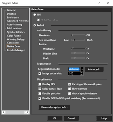
GDI Options
Flicker Free Draw: When this option is turned on the redrawing of entities is made smoother, however, this can marginally slow down zooming and panning of drawings.
Redsdk Options
Hardware: Creates an anti-aliasing effect on 2D graphics elements. The values available are: Off, 1x, 2x, 4x, 8x, 16x. Turning this on will make the display smoother, but lowers the performance. Vertical Synchronization: Makes the display looking better, while moving, however it may higher memory usage. Text Smoothing: Turning this on will make the display of text smoother, but lowers the performance. Engine:
- Wireframe - Sets the engine anti-aliasing in Wireframe mode. Range – [1-5]. By default – 1. Enabled if Redsdk is On.
- Hidden Lines - Sets the engine anti-aliasing in Hidden Line mode. Range – [1-5]. By default – 2. Enabled – if Redsdk is On.
- Draft - Sets the engine anti-aliasing in Draft Render mode. Range – [1-5]. By default – 2.
Show Video System Info: Pressing this button will display the current video card setup on your computer. If your current driver for the video card is not the optimal driver for Redsdk you will be prompted to download the correct driver via a link within the window. If you do not download the optimal Redsdk will use a default driver. 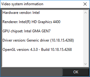
Regeneration
To optimize performance Redsdk will delay the regeneration of some drawn elements during movements such as panning or zooming. Regeneration Mode: You can specify that regeneration is Manual, or automatic. If set to manual all delayed elements will not be regenerated until you press F5 or select Regen or Redraw from the menu. The Advanced settings for Regeneration allow you to specify which items are optimized and which are not. Image cache after: Specifies the size (in MB) after which rendered images will be cached. Advanced: Settings for Regeneration allow you to specify which items are optimized and which are not. 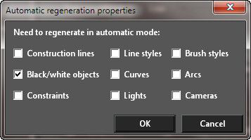
Miscellaneous
Display FPS: If this option is on a display appears in the upper right corner of the drawing space. This display tracks the Frame Per Second to indicate the speed of the Redsdk drawing engine. Delay Surface Load: Delays the loading of surfaces and objects until rendering to optimize memory usage. Caching of Model Space: Store the contents of the model space in the cache to optimize presentation. Disable GDI/RedSDK quick switching (recommended): When checked, the program will be forced to restart when switching between RedSDK and GDI (either direction). This is the recommended setting. If unchecked, you can switch without restarting, but minor display problems, etc. have occurred when doing so. Show Normals: When on this option causes Normals to be displayed on all 3D and Surface objects.
Note: Redsdk is dependant upon video cards which support OpenGL acceleration, and the features of that card. If you do not have an OpenGL video card you will not be able to use Redsdk. Recommended: Switching between GDI mode and Redsdk will require a restart of TurboCAD. Note: Redsdk conflicts with GDI's native support for OpenGL hardware acceleration If you switch to Redsdk you will be prompted to allow TurboCAD to turn native OpenGL hardware acceleration off. With Redsdk turned on the Camera Properties "Renderable objects" is always disabled, "Suppress Hidden Line" is always enabled for all pages except the Wireframe page in Camera Properties Dialog.
Show Normals
The Show Normals setting is found under Program Setup/Native Draw. It is Off by default. The visualization of the normals makes it easier to estimate the smoothness and orientation of the 3D objects and to find artifacts/defects on those objects. 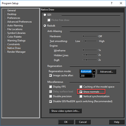 When this option is On the normals are drawn in red color at the vertices of the 3D objects.
 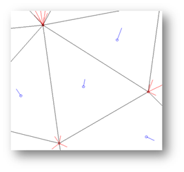 Normals are drawn in blue at the center of facets and show the direction each facet is facing. The direction of each normal is determined by the path that the edges of each facet take as they wind around the face. The calculation uses the right-hand rule to determine the normal. The size of the normals is approximately 1/10 the size of the surface bounding sphere's radius (the smallest sphere that will enclose the object). In other words, the size of the normal is directly proportional to the size of the object. The direction of the normals take into account the option Reversed Normals which is found in the 3D properties dialog of each object.
 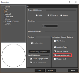 The base polygon of the normals are displayed takes into account the option Double Sided which is found in the 3D properties dialog of each object. Double-Sided objects show a double polygon. Normals for Double and Single sided primitives
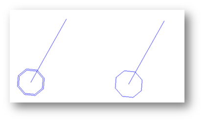
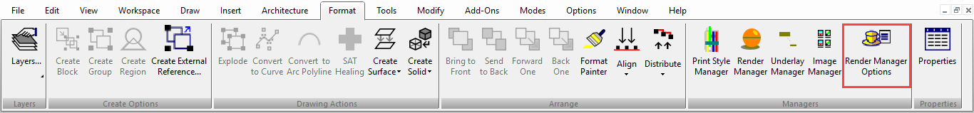
Render Manager Options
Default UI Menu: Options/Program Setup/Render Manager
Ribbon UI Menu:
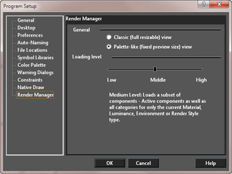
General
You can specify how the Render Manager is displayed by selecting either Classic or Palette-Like
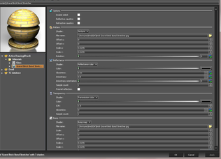
Classic
- Variable sized preview.
- Tree can be hidden.
- Each category of components is displayed on separate tabs.
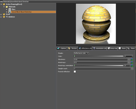
Palette-like
- Fixed square preview area (240x240)
- The tree cannot be hidden.
- While resizing the dialog, only the tree's height, and the properties area size change.
- All properties of the main shader are shown on one page. Components of sub shaders are shown on separate pages.
The Palette-like option is always used when the Render manager is accessed from object properties.
| Palettle-like | Classic |
|---|---|
 |
 |
Low Level: Loads the minimal set of components - Active components ‐ Active components as well as those for the components in only the current type's ﴾Material, Luminance, Environment or Render Style﴿ category. Medium Level: Loads a subset of components ‐ Active components as well as all categories for only the current Material, Luminance, Environment or Render Style type. High Level: Loads a full set of components ‐ All Active components as well as all types and categories.
How these function:
| Low | Medium | High | |
|---|---|---|---|
| Called from application menu | Load only one shader set type (for ex. only materials) | Load all of one shaders set type (for ex. only materials) | Load all shaders sets of all types |
| Called from palette – selection exists | Equal to the "Single Entrance" | Load all of one shaders set type (for ex. only materials) | Load all shaders sets of all types |
| Called from palette – no selection | Load only one category | Load all of one shaders set type (for ex. only materials) | Load all shaders sets of all types |
The Filter options in the respective palettes (Materials, Luminances etc.) will further control what will be loaded into the Render manager. As follows:
| Show Only Active drawing shader manager | Show all open Drawing Shaders managers | Show Application Shaders manager | |
|---|---|---|---|
| Called from application menu | No | No | Yes |
| Called from palette | Yes | Yes (if "Show all drawings" is checked) | Yes (if "Show all drawings" is checked) |
Choosing the Render Engine for loading in Render Manager
| RedSDK | LightWorks | Both | |
|---|---|---|---|
| Called from application menu | Yes (if "Edit RedSDK…" was pressed) | Yes (if "Edit LightWorks…" was pressed) | No |
| Called from palette | Yes (if "RW" filtration button is pressed) | Yes (if "LW" filtration button is pressed) | Yes (if "All" filtration button is pressed) |
Advanced Preferences
Default UI Menu: Options/Program Setup/Advanced Preferences
Ribbon UI Menu:
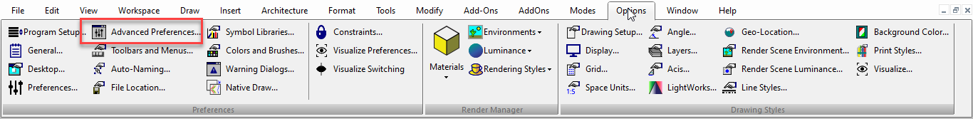
Advanced options for program control. 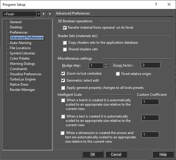
3D Boolean operations
Transfer material from operand on its facet: When checked, material from one object is transferred onto the other during a 3D Boolean operation (3D add, 3D subtract, etc.). When unchecked, the materials are not affected on either object.
Shader Sets
Copy shaders set to the application database: Sometimes it will be desirable to copy shaders from a drawing into the Application Shaders Manager. To resolve this issue there is an option on the 'Preferences' page. By default, this option is off. When this option is active when a file is opened all shaders sets will not only be added to the Model Shaders manager but also will be copied to the Application Shaders Manager. It is a not advisable to keep this option always active because if it is the Application Shaders Manager will gradually turn into a "trash bin". So the best way to use this option is to turn it on before opening the desired file and then turn it off again. Shared shaders set: This option defines the scheme of work with the render attributes (material, luminance, environment, render style). By default, it is off. Note: After changing this option it is necessary to restart TurboCAD.
If this option is ON, then all operations with the render attributes occur according to the "old scheme", which was used before TurboCAD 2016. Namely, the changing of a shader attribute in one drawing leads to the changing in all drawings and in the application database. Also, the local menus in the palettes and in the Render Manager for that attribute are changed. For example in the local menu of the materials palette the two items are removed (marked by green): 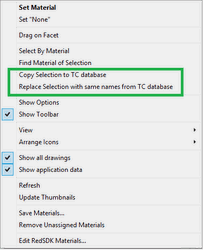 In the Render Manager, the local menu for the material from the drawing will be absent.
Miscellaneous settings
Nudge Step: Sets the distance that a nudge will move an object. Values are specified in Pixels.
Zoom factor: Controls how much you zoom in or out of the drawing when you use View / Zoom In or Zoom Out. The default zoom step setting is 2, meaning that zooming in doubles the size. See Zoom In and Zoom Out. Zoom In/Out Centralize: When this feature is On (default), rolling the mouse wheel will zoom in/out and centralize the view & cursor at the center of the drawing area. When this is Off, rolling the wheel will zoom in/out at the location of the cursor. Fixed relative origin: If checked, the relative origin will be fixed while in relative or polar coordinates. If you need to relocate the origin, it must be done manually. See Relative Coordinates and Polar Coordinates. Geometric select edit: If checked, objects will be selected by their geometric extents, rather than their cosmetic extents. This permits geometrically accurate scaling of objects like double lines and lines that have nonzero width. See Geometric and Cosmetic Select Modes?. Apply general property changes to all tools presets: Enables the Property toolbar to change all styles for all tools.
Intelligent Scale
Hatch: When a hatch is created it is automatically scaled to an appropriate size relative to the current view. This means in particular to the level of zoom. Text: When a text is created it is automatically scaled to an appropriate size relative to the current view. This means in particular to the level of zoom. Dimension: When a dimension is created it is automatically scaled to an appropriate size relative to the current view. This means in particular to the level of zoom. Custom Coefficient: This is a scaling multiple that is applied to the intelligent scaling. For example, 2 would double the size whereas 0.5 would halve the size.
Draw by Layer
Options| Advanced Preferences
The Draw by Layer functionality is activated by selecting the Apply general property changes to all tool presets check box. This affects how tools relate to general properties such as Layer, Line Color, Line Width, Line Pattern etc. When active, changing any of those properties, while using a tool, will change that property for all tools in the same way. When inactive the application will behave in its traditional manner. This means that the layer setting for other tools will be unaffected, and changes to other tool properties, like Line Color, will only affect related tools. For example, changing the color of the Line tool affects the color of all line tools.