Profile Objects and Face to Face Modification
Profile objects are based on existing 2D objects. The original 2D profile remains unmodified by the 3D tool that references it. One advantage to profile objects is that you can change them by simply editing the profile (or profiles) on which they are based. See Profile Editing
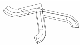
Branched Lofting
(Available only in Platinum)
Default UI Menu: Draw/3D Object/3D Profile Based/ Lofts/Branched Lofting
Ribbon UI Menu:
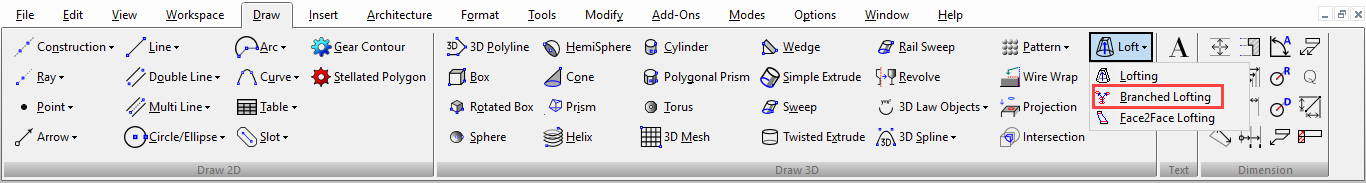
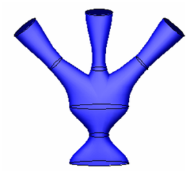
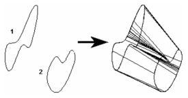
Creates a lofting object by defining profiles along a trunk, and profiles along two or more branches. The profiles lie on different planes, and the planes do not have to be parallel. The result is one 3D object.
- Select the profiles that define the trunk. The branching will start at the last profile of the trunk.
- Select Finish selection of trunk from the local menu or Inspector Bar.
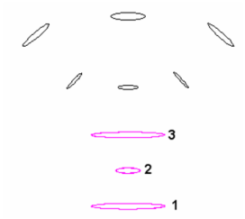
- Select the profiles that define the first branch, starting at the profile closest to the end of the trunk.
- Select Finish selection of branch.
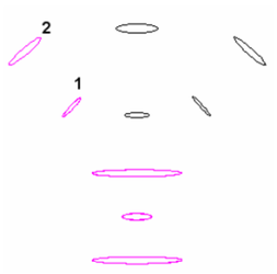
- Select profiles for additional branches the same way.
- When all branches are defined, select Finish. The lofting object is created.
Compound Profiles
(Available in Platinum)
A compound profile is an open or closed chain of connected curves or lines, or any set of closed curves or closed polylines. You can use compound profiles when you do not want to create a polyline or convert a chain into a polyline. Compound profiles can be used as paths for sweeps etc. and as profiles that are swept along paths. You can use blocks as compound profiles, however, there are restrictions. You can only only use one element in a block as a path for any given operation. Also, only closed sequences of curves, lines etc. (chains) or closed objects can be used to sweep, revolve etc. All such closed objects in the block selected to sweep, revolve, etc will used in the resulting 3D object.
Extrude to Face
(Available only in Platinum)
Default UI Menu: Modify/Modify 3D Objects/ Extrude to Face
Ribbon UI Menu:

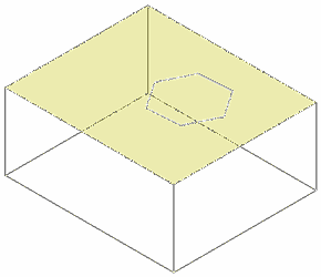
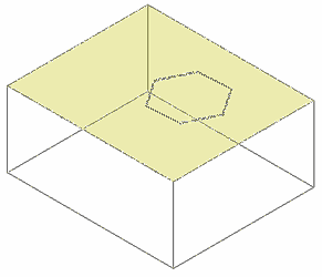
Extends a 3D object by extruding selected faces to a selected 3D object and performing a boolean.
- Select the face of a 3D object.
- Select the 3D object to be the target of the extrusion.
- The result is a new 3D object.
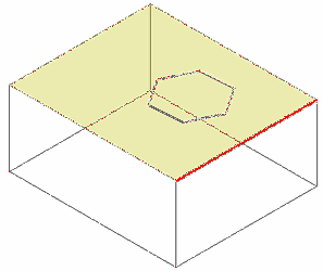
If the boolean option is set to Subtract, the extrusion will be subtracted from the target body, and the original 3D object from which the extrusion was made will be removed.
You can extrude multiple faces at one time, but you can extrude to only a single 3D object.
- Hold down the SHIFT key to select multiple faces.
- Release the SHIFT key and select the target object.
- You will have a multiple extension.
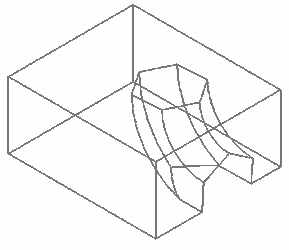
There are some limitations that must be respected to create valid result. Resulting extrusions must intersect the target body when extended, or the operation will be invalid. You cannot extrude adjacent faces. Adjacent faces are extended along with the extrusion face. Adjacent curved faces and adjacent slanted faces will continue their curve or slant when the selected face it extruded .
You can extend to ACIS surfaces, but only if the target body completely intersects the resulting extrusion.
You cannot extrude a face to the same 3D object that the extrusion face belongs to.
When extruding to a ACIS surface you can remove the remnant "excess" of the target surface using the Facet Edit tool.
- Select the facet.
- Press the DELETE key.

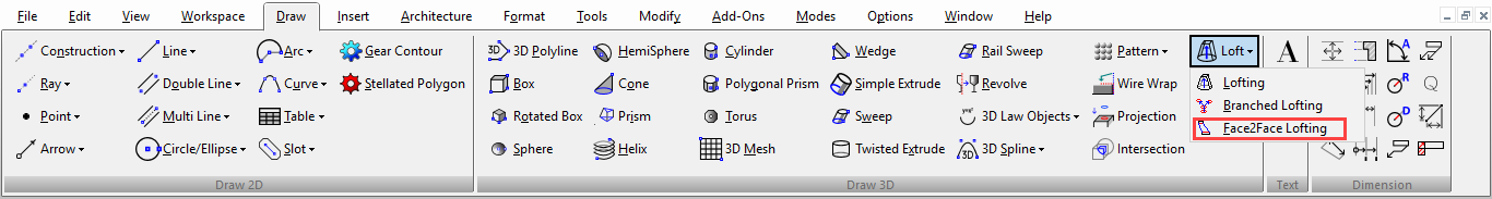
Face2Face Lofting
(Available only in Platinum)
Default UI Menu: Draw/3D Object/3D Profile Based/Lofts/Face2Face Lofting
Ribbon UI Menu:
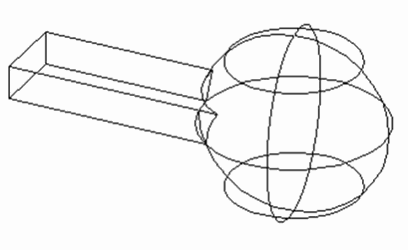
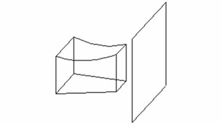
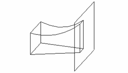
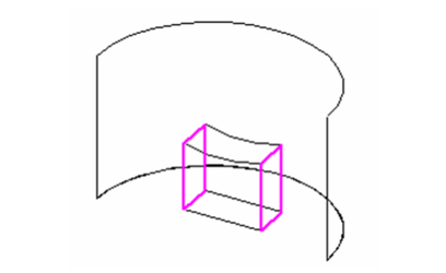
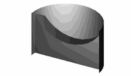
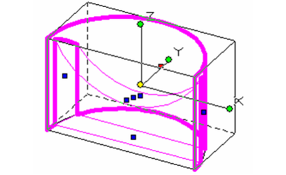
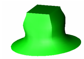
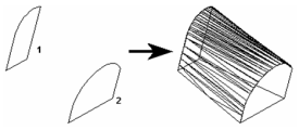
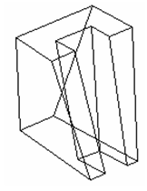
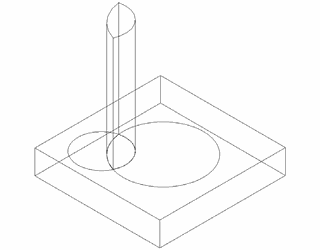
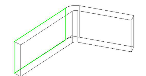
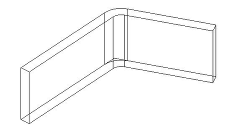
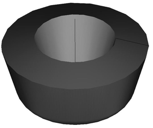
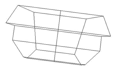
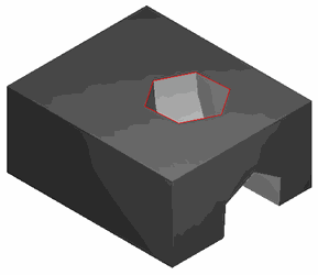
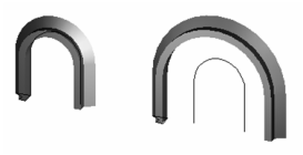
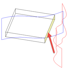
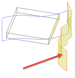
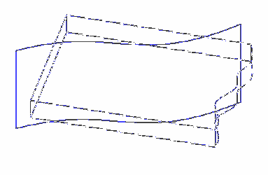
Creates a 3D lofting object between two faces of existing 3D objects. The result is one 3D object.
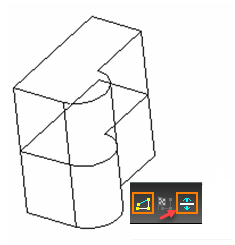
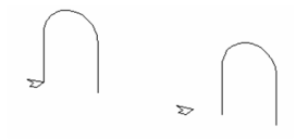
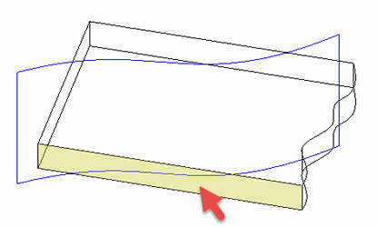
- Select the first face, in this example, the top of the cylinder. Selection order is important.
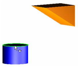
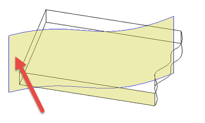
- Select the second face, in this case, the sloped face of the wedge.
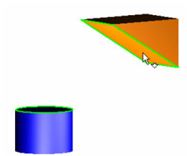
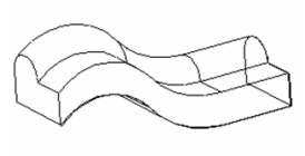
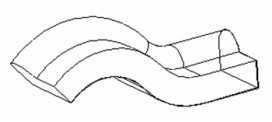
- The result is a loft object that proceeds smoothly between the two faces. The two original objects and the new loft object are now merged into one object.
The resulting object takes the properties (such as Pen) of the object where you selected the first face.
Graphic On Path
(Available only in Platinum)
Default UI Menu: Modify/Modify 3D Objects/3D Assemble/Graphic on Path
Ribbon UI Menu:
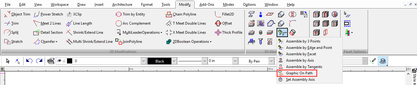
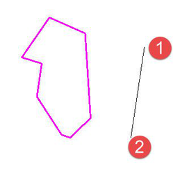
Places a 2D profile or 3D object along a 2D or 3D path.
- Select the profile or object you want to project, then select a point on the path where you want the projection.

- Click more points where you want profile projections.

If you rotate the model, you can see the profiles in 3D.
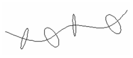
- Select Finish from the local menu or Inspector Bar to exit the function.
Local menu options: Sets: Specifies a number of copies of the object that will be placed from the insertion point onward. The space between the insertions will be equal to the value in the Distance field. Distance: Set the distance between the multiple insertions specified by the Sets field. Delete Original: Deleted the original object. Flip Original: Flips the inserted objects, creating a mirror of the original. Set Graphic on Path Start Point: Sets the insertion at the start point of the path. Set Graphic on Path End Point: Sets the insertion at the end point of the path. Sets will be ignored if this setting is on.
Lofting
(Available only in Platinum)
Default UI Menu: Draw/3D Object/3D Profile Based/Lofts/Lofting
Ribbon UI Menu:
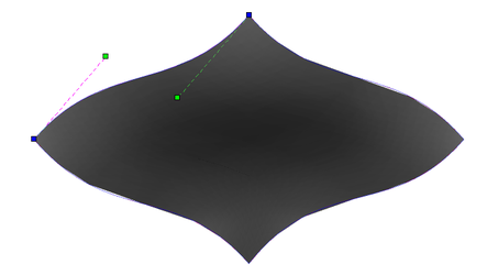
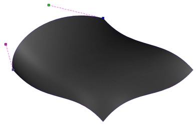
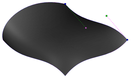
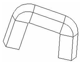
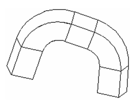
Creates a 3D object by connecting 2D profiles. The profiles lie on different planes, and the planes do not have to be parallel. The profiles are connected using NURBS (Non-Uniform Rational b-Spline) calculations. The profiles can be closed or open, but they must be consistent - all open or all closed.
- If you want to select only simple (single-object) curves, make sure Use Compound Profile is not selected.

- Select the profiles, in the desired order. Selection order is important
- Select Finish from the local menu, or double-click on the last profile, to create the loft.
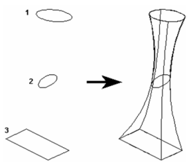
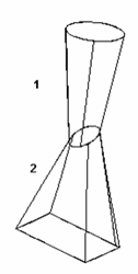
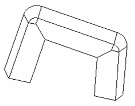
The loft has no sharp corners at the profiles. To create corners, you can creates two separate lofts.
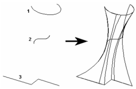
If you use open profiles, a 3D surface will result.
Lofting with Compound Profiles A compound profile is an open or closed chain of connected curves. You can use compound profiles when you do not want to create a polyline, or convert a chain into a polyline.
- Make sure Use Compound Profile is selected.

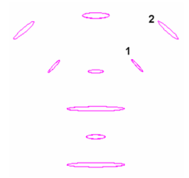
- Select the compound profile, which is automatically identified as a chain. To select individual segments hold down the CTRL key and click it, to de-select click it again with the CTRL key. In this example, Profile 1 is a series of connected lines, not a polyline. NOTE: if you select individual segments you will be prompted to Finish the selection of the profile.
- Select the next profiles using the same steps. If subsequent profiles are simple (not compound), you can turn off Use Compound Profile.
- When the last profile is selected, click Finish or select it from the local menu.
Note: Compound profiles can be modified, which updates the 3D objects upon which they are based. See Profile Editing
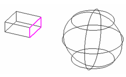
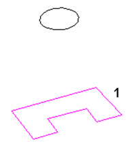
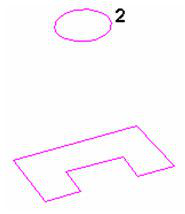
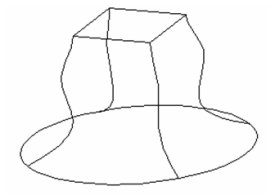
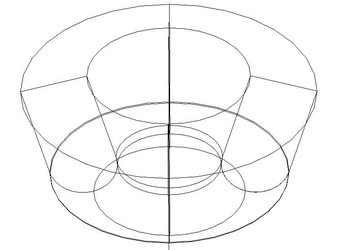
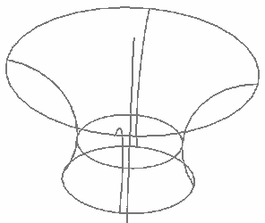
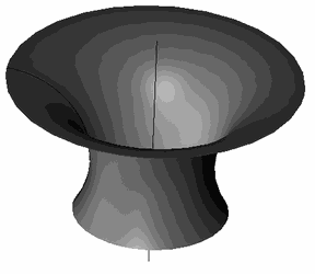
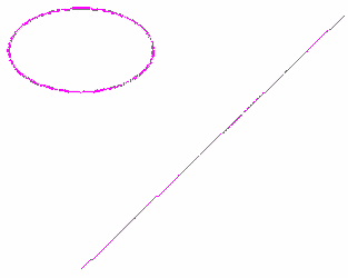
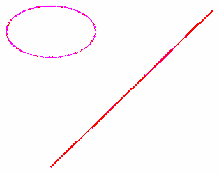
- Lofting with Guide Lines You can specify guides lines when creating the loft object. In this example, the lower circle and upper square are the loft profiles. The four curves between the profiles are guide lines.
- Activate Loft, and select the loft profiles in the desired order.
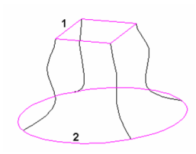
- Click Select Guide Lines, or select it from the local menu.
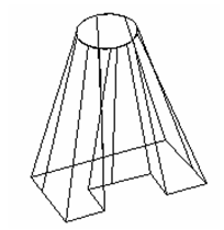
- Select each of the guide lines.
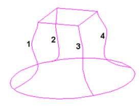
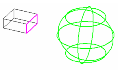
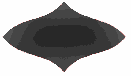
- Click Finish or select it from the local menu. The 3D object transitions between the loft profiles, following each of the guide lines.
Guide Lines: Guide lines can be arcs, 2D or 3D Splines or lines. Beziers, and polyline cannot be used as guide lines. Guide line must touch every profile used in the loft. One end of each guide line must terminate on the first profile used in the loft The other end of that guide line must terminate on the last profile used in the loft. If guide lines do not meet these requirements they will be ignored.
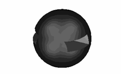
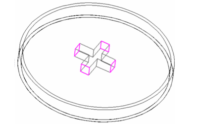
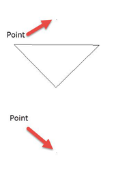
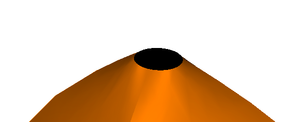
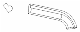
Lofting with Points
Points can be used in lofting. Note: Shaped points may be used but not the cross shape.
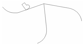
 Result:
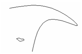
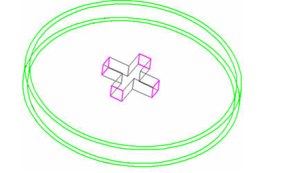
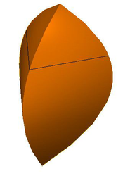 The shape of the point effects the shape of the resulting loft.

Lofting Shape Properties
The Properties window of a loft contains a Lofting Shape page, in which you can minimize twist. 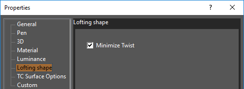 Minimize Twist
Effect of Minimize Twist For TC Surface Options, see TC Surface Properties)
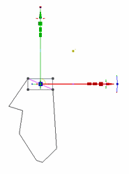
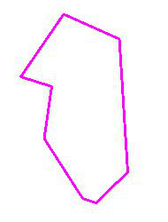
Editing Profiles
If you used the compound profile option in the selection of the profiles and/or the guidelines you can post edit them via Edit node. 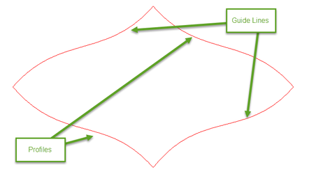

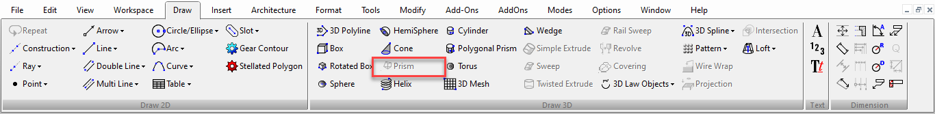
Prism

(Available in Platinum, Professional and Deluxe)
Default UI Menu: Draw/3D Object/3D Profile Based/Prism
Ribbon UI Menu:
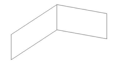
Creates a 3D object between two 2D objects that lie on different planes. The planes do not have to be parallel. Both profile objects must be the same type and must have the same number of vertices. For example, you can create a prism between two circles or two rectangles, but not between a circle and a rectangle Splines and Bezier curves must have the same number of control points.
Note: A prism is considered to be a Lofting object, and its Properties contain a Lofting Shape page.
- If you want to select only simple (single-object) curves, make sure Use Compound Profile is not selected.

- Select the two 2D objects.
Polyline to polyline
Spline to spline
You do not have to select closed 2D objects. If you use open objects, a 3D surface will result.
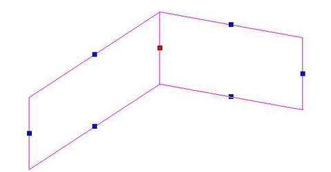
Prism with Compound Profiles: A compound profile is an open or closed chain of connected curves or lines. You can use compound profiles when you do not want to create a polyline, or convert a chain into a polyline.
- Make sure Use Compound Profile is selected.

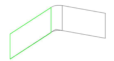
- Select the first compound profile, which is automatically identified as a chain. To deselect any curve in the chain, select it again (it will turn green). In this example, Profile 1 is a series of connected lines, not a polyline.
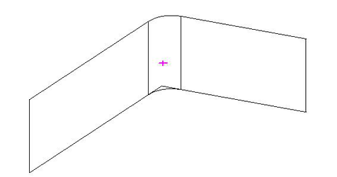
- When the profile is selected, click Finish Selection of Profile, or select it from the local menu.

- Select the second profile using the same steps.
- When you finish the second profile selection, the prism is created.
Note: Compound profiles can be modified, which updates the 3D objects upon which they are based.
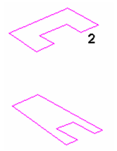
Profile Along Path
(Available in Platinum and Professional)
Places a 2D profile along a 2D or 3D path.
Default UI Menu: Draw/Profile Along Path
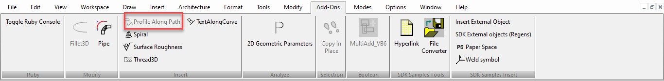
Ribbon UI Menu:
- Select the profile you want to project, then select a point on the path where you want the projection.
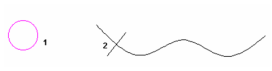
- Click more points where you want profile projections.
If you rotate the model, you can see the profiles in 3D.

- Select Finish from the local menu or Inspector Bar to exit the function.
Local menu options: Make Copy Profile: Use this profile to make multiple copies along the path. When deselected, you can Finish or select another profile. 
One Step Back: Removes profiles in the reverse order in which they were created on the path.

Unselect Profile: Unselects the current profile, enabling you to select another one. 
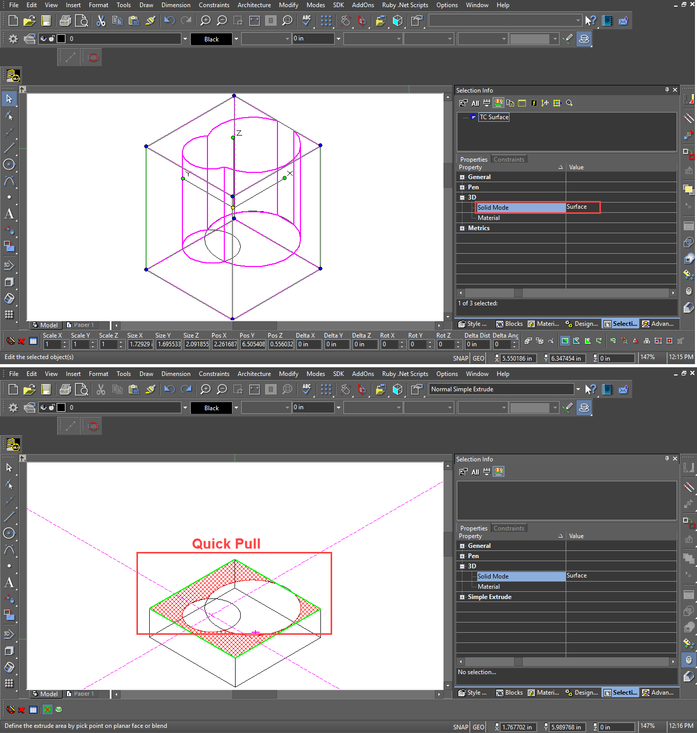
Quick Pull
(Available in Platinum, Professional and Deluxe)
Default UI Menu: Modify/Modify 3D Objects/Quick Pull
Ribbon UI Menu:
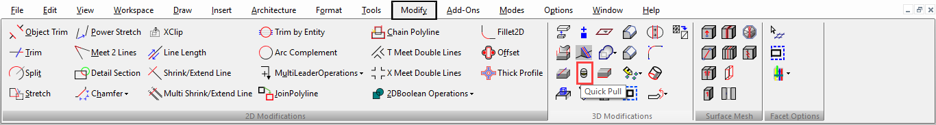
Pulls or pushes a 3D extension of a face (of either a TC Solid or a TC Surface) by extruding a 2D closed area on the face of a 3D object. The extrusion extends along a path normal to the face of the 3D object.
The closed area must be co-planar with the Flat face of a 3D object. It may consist of:
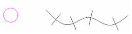
- Any closed 2D entity. E.g. a rectangle.
- Any area that can be hatched by picking a point (with zero gap tolerance).
- Areas enclosed by crossing co-planar, linear geometry, including edges and geometry in blocks E.g. intersecting lines that create a closure.
- 3D faces. E.g. The face of a cube
- Any combination of the above.
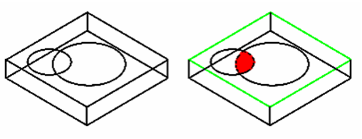
Areas created by geometry (including edges on faces) drawn co-planar to any face of a 3D solid E.g. A circle is co-planar with the face of a cube. It overlaps the edge of the cube. The edge divides the circle into two parts, one is a valid area, or intersecting lines that create a closure on the face of a 3D object, with or without defining geometry of the 3D entity
- Select the 2D closed area to extrude.
- Move the mouse to extrude the face, or enter a value in the Height field of the Inspector Bar.
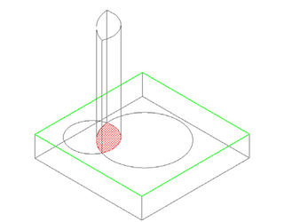
- If you are specifying the height by using the mouse, click to finish the extrusion. Or If you are specifying the height by using the height field in the Inspector bar, press Enter to finish the extrusion.
Note: If the Two Sided property is set, the solid extrusion will be created on either side of the profile.
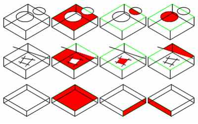
Examples of areas that can be extruded:
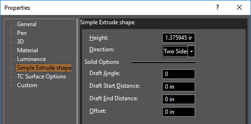
Quick Pull Properties
The Properties window of an Quick Pull object contains a Simple Extrude Shape page, in which you can set parameters defining how the object is created. Height: The distance of the extrusion. Direction: Switch between one-sided and two-sided. Solid Options: For these parameters to be accessible, the extrusion must be created as a solid. Draft Angle: Creates an extrusion of increasing or decreasing cross-section. Enter the angle of deviation from the extrusion path. Draft Start / End Distance: If Draft Angle = 0, you can specify a draft angle by entering the draft distances. Offset: Creates a hole in the extrusion at a distance from the outside of the extrusion equal to the Offset value. The Quick Pull and the Simple Extrude tool use the same Property Value Preset. Therefore, changing the property settings in one tool will change the settings in the other.
Quick Pull and 2D Surfaces
You can use The Quick Pull tool to thicken a flat 2D surface. (This must be an ACIS solid / TC surface)
 For example,
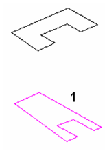
- Take a 2D Polyline
- Extrude it with the Simple Extrude tool
- Fillet the corner.
- Then use the Push mode of the Quick Pull tool to give it some thickness.
View the following video for more info on using the the Quick Pull tool on TC Surface.
Demo Video:
https://youtu.be/Zoy-MIygXHI
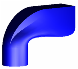
Pulling Curved Faces
Curved faces can also be pulled with the Quick Pull tool. However there are some limitations.
- Only faces which have circular curves can be pulled. E.g. Cylinders, Fillets, and Bends.
- Elliptical, spline, Bezier or spherical surfaces cannot be pulled.
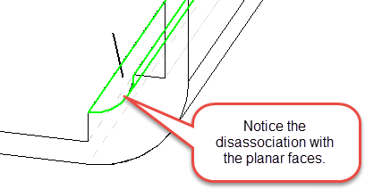
- A curved surface will normally disassociate tangency from adjacent planar surfaces when it is pulled.
- Interlocked adjacent curved cases can prevent this from functioning.
To use the Quick Pull on a curve: Select the tool. Hover over the desired surface until it highlights. 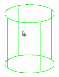 Click on the surface. Move the cursor left of right to push or pull the face in or out. Alternately you can TAB into the Inspector bar, enter a new radius and press ENTER.
 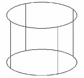 Click to set the new radius.
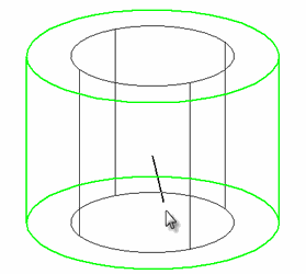
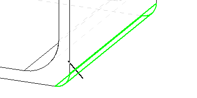
Fillets
Click on the surface. 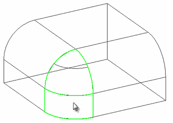 Move the cursor left of right to push or pull the face in or out. Alternately you can TAB into the Inspector bar, enter a new radius and press ENTER.
 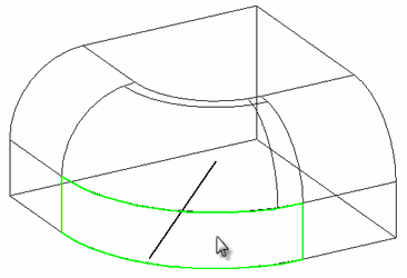 Click to set the new radius.
 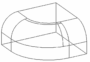 There are some limitations While it is possible to select the face below it cannot be pulled because it is locked by the adjacent fillet.
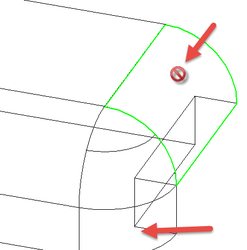
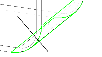
Fillet - Detect Blend network
 An additional option for pulling fillets is Detect Blend Network. When this option is On all adjacent fillets will be pulled simultaneously. Click on the surface.
 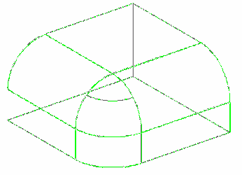 Move the cursor left of right to push or pull the face in or out. Alternately you can TAB into the Inspector bar, enter a new radius and press ENTER.
 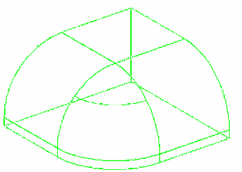 Click to set the new radius.
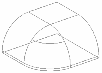
Bends
Below are some use cases for pulling bends. 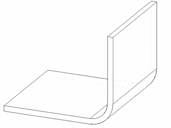
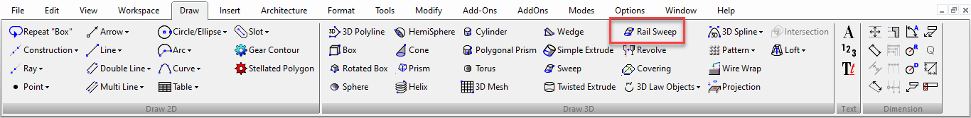
Rail Sweep
(Available in Platinum, Professional and Deluxe)
Default UI Menu: Draw/3D Object/3D Profile Based/Rail Sweep
Ribbon UI Menu:
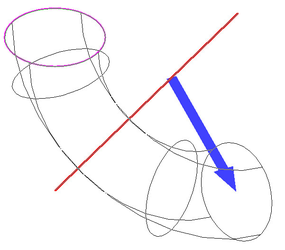
Creates a 3D object by driving a 2D profile along a path. The profile and path do not have to touch or be in different workplanes; the profile section will be "brought" to the start of the path, made normal to the path, and swept along it.
Base Point
If you are going to use Compound profiles for both the path and the profile you will need a base point. The base point specifies the point though which the profile will follow the path. To create a base point, use the Point tool and place a point at the location adjacent to the profile that you wish to be used. For example, at the end of a line, or at the center of an arc or circle.
Creating a Rail Sweep
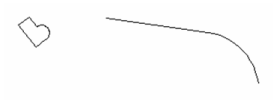
- Start with one 2D profile. The profile can be open or closed. Add a 2D or 3D path. The path can lie anywhere, and in any workplane. In this example, profile and path lie in the same workplane.
- Activate Rail Sweep.
- If the profiles consist of compound curves, make sure Use Compound Profile is active.

- Select the first 2D profile. If the profile is open, select Finish Selection of Path to end the selection. You can then select more profiles if necessary, by pressing the Shift key.
- If you are using a Compound profile for the profile you must specify the base point to be used. At this step select the point you created for this purpose.
- Then select the sweep path. If the sweep path consists of more than one curve, make sure Use Compound Profile is active.

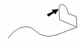
- The profile is brought to the path (at the base point if one is being used) and swept along it, normal to the path. The profile intersects the path at its reference point.
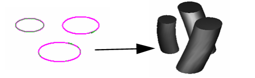
This tool is handy if you have a single profile that you want to sweep over multiple paths, or rails. In this example, there are three paths for the same profile:
Here are the results:
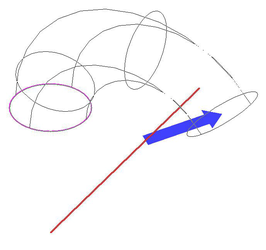
If you used a Compound profile for the profile, you will be able to modify the resulting 3D object by modifying the original profile object or by moving the base point object. If you used a Compound profile for the path, you will be able to modify the resulting 3D object by modifying the original path object/s. The sweep path does not have to be 2D the path in this example was created using 3D Spline by Fit Points.
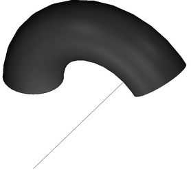
This is the result:
Local menu option Rigid Sweep: Keeps cross-sections of the solid parallel to one another along the entire path.
Compound Profiles as Paths
You can also use a compound profile as a path
Revolve
(Available in Platinum, Professional and Deluxe)
Default UI Menu: Draw/3D Object/3D Profile Based/Revolve
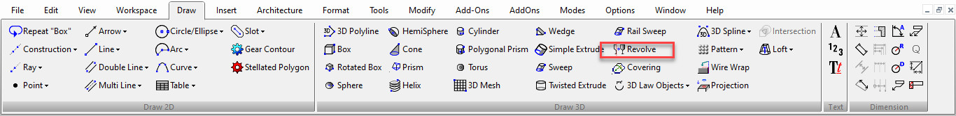
Ribbon UI Menu:
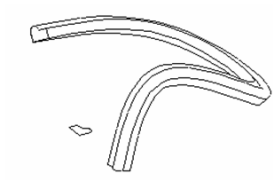
Creates a 3D object by revolving a 2D object about a revolution axis, or revolves a 2D object to make a solid imprint on an existing solid via Booleans. By default, the profile will be revolved 360 degrees, but you can change this angle or create a spiral.
- If you want to select only a simple (single-object) curve, make sure Use Compound Profile is not selected.
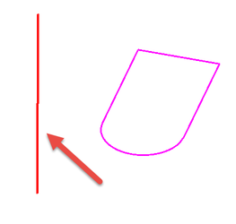
- If you want to select a line as the axis of revolution, make sure Select Revolve Axis is active

- Select a 2D object to revolve.
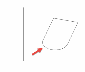
- Select two points of a revolution axis or if Select Revolve Axis is active, select the axis line..
The revolved shape is created.
Straight edges of solids can also be used as a revolve axis line. 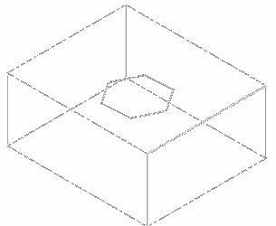
You do not have to select a closed 2D object to revolve. If you use an open object, a 3D surface will result.
Revolve with Compound Profiles
A compound profile is an open or closed chain of connected curves. You can use compound profiles when you do not want to create a polyline, or convert a chain into a polyline.
- Make sure Use Compound Profile is selected.

- Select the compound profile, which is automatically identified as a chain. To deselect any curve in the chain, select it again (it will turn green). In this example, the profile is a series of connected lines, not
a polyline.
- You can select more profiles if necessary. When the profiles are selected, click Finish Selection of Profile, or select it from the local menu.

- Select two points of a revolution axis, or, if Select Revolve Axis is active, select the axis line.
The revolved shape is created.
Note: Compound profiles can be modified, which updates the 3D objects upon which they are based.
Revolve with Specified Angle
You can revolve with a specified angle and direction.
- Select the tool.
- Select the Define revolve angle option.
- Select the profile.
- Select two points of a revolution axis, or, if Select Revolve Axis is active, select the axis line.
- Click to specify the angle or specify the angle in the inspector bar.

- You can also reverse the direction by changing to the Revolve Clockwise or Revolve Counterclockwise option in the Inspector bar or the Local menu.
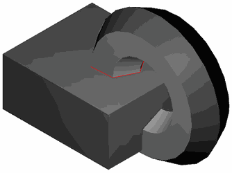
Revolve with Imprint
You can revolve a 2D profile to make a solid imprint on an existing solid via Booleans. The Profile must be on the face of the existing solid.
- Select the tool.
- Select the Create Imprint option in the Inspector bar or the Local menu.

- Select the Imprint type Subtract option in the Inspector bar or the Local menu.
- Make sure Select Revolve Axis is active.

- Select the face that the 2D profile is on.
- Select the 2D profile.
- Select the edge of the solid.
Result:
If the Result if the Imprint type Add was selected.
Revolution Shape Properties
The Properties window of a revolve contains a Revolution Shape page, in which you can set geometric parameters.
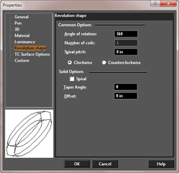
For the Solid parameters to be accessible, the Revolve must be created as a solid. In the 3D page of the Properties window, make sure Solid is selected under Create Object As. Solid Options: Spiral: The revolution will proceed outward in a spiral pattern Taper Angle: The revolution will have a draft angle, with the section increasing or decreasing at it progresses. The remaining parameters (Common Options) appear for both surface and solid objects Common Options: Angle of rotations: Enter a value less than 360 for a partial revolve. Spiral pitch: The lateral distance between the start and end of the revolve, enabling you to create a spiral. The angle of rotation must be 360.
Number of coils: If Spiral pitch is nonzero, you can specify the total number of revolutions.
Clockwise/Counterclockwise: Sets the direction of revolution. The direction depends on how the revolution axis was selected. For TC Surface Options, see TC Surface Properties
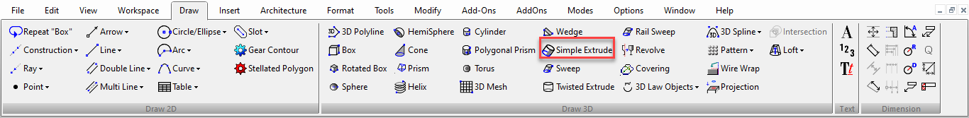
Simple Extrude
(Available in Platinum, Professional and Deluxe)
Default UI Menu: Draw/3D Object/3D Profile Based/Simple Extrude
Ribbon UI Menu:
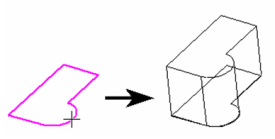
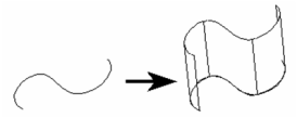
Creates a 3D object by extruding (sweeping) a 2D open or closed profile along a path normal to the workplane of the 2D object. If you extrude an open profile, a surface will be created.
- If you want to select only a simple (single-object) curve, make sure Use Compound Profile is not selected.
- If you want to use a compound profile, which is a series of connected lines and/or arcs, select Use Compound Profile.

- If necessary, select Finish Selection of Profile to continue.
- Select the 2D open or closed profile to extrude. Move the mouse to extrude the profile, or enter a value in the Height field of the Inspector Bar.
If you select an open profile, the resulting 3D object will be a surface.
If you select , the solid extrusion will be created on either side of the profile.
Extruding Multiple Profiles You can also select multiple closed regions, or profiles, to extrude all at one time. Make sure Use Compound Profile is selected. Select the first profile, then press Shift to select additional profiles. Each profile is extruded the same distance.

If you select nested regions, you can create islands, and regions within islands. 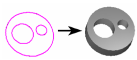
Note: Compound profiles can be modified, which updates the 3D objects upon which they are based.
Simple Extrude Shape Properties
The Properties window of an extrude object contains a Simple Extrude Shape page, in which you can set parameters defining how the object is created.
 Height: The distance of the extrusion. Direction: Switch between one-sided and two-sided. Solid Options: For these parameters to be accessible, the extrude must be created as a solid. Draft Angle: Creates an extrusion of increasing or decreasing cross-section. Enter the angle of deviation from the extrusion path.
Draft Start / End Distance: If Draft Angle = 0, you can specify a draft angle by entering the offset distances. Offset: Creates a hole in the extrusion at a distance from the outside of the extrusion equal to the Offset value. For TC Surface Options, see TC Surface Properties
Note: Text can be used as part of a compound profile while extruding.
Now we can select flat 3d polylines or 3d curves for surface extrude(revolve) tools. Also, separated 3d curve and curve (2d curve) have been separated.
Demo Video: You can learn more about Surface Extrude improvements in TurboCAD from below video.
https://youtu.be/Aqh18XqeYD4
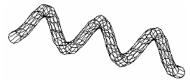
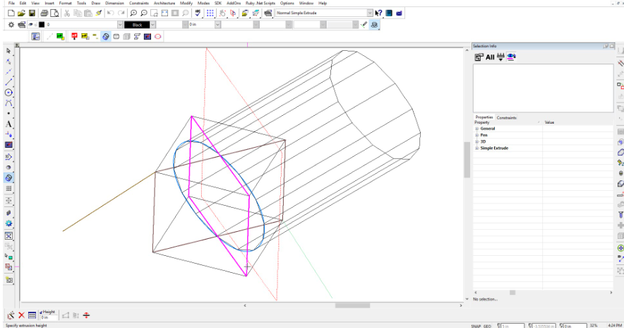
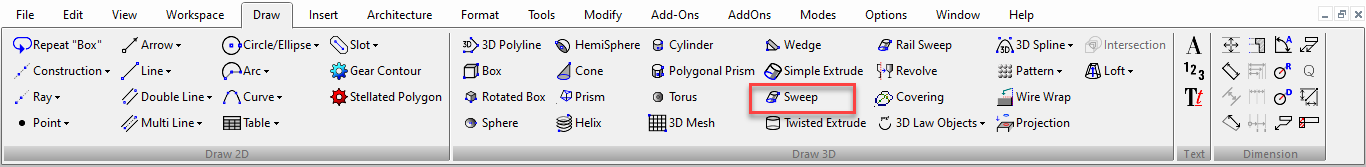
Sweep
(Available only in Platinum)
Default UI Menu: Draw/3D Object/3D Profile Based/Sweep
Ribbon UI Menu:
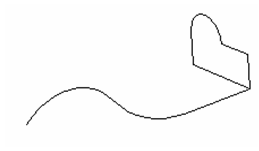
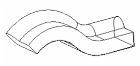
Creates a 3D object by driving a 2D profile along a path.
- Start with one or more 2D profiles. The profiles can be open or closed. Add a 2D or 3D path. Typically the path intersects the profile and is approximately perpendicular to it, but these conditions are not required.
- Activate Sweep. If the profiles consist of compound curves, make sure Use Compound Profile is active.

- Select the first 2D profile. If the profile is open, select Finish Selection of Path to end the selection. You can then select more profiles if necessary, by pressing the Shift key.
- Then select the 2D or 3D path over which you want to sweep the 2D profiles. If the sweep path consists of more than one curve, make sure Use Compound Path is active. When finished, click Finish Selection of Path.
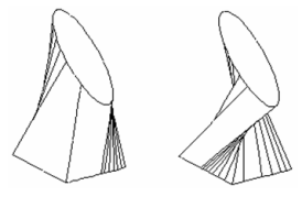
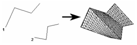
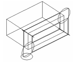
As stated before, the 2D profile and the sweep path do not have to intersect. However, the results will vary depending on how far apart the profiles are. Consider this comparison, in which the profiles on the left intersect and the profiles on the right do not.
Here are the Sweep results: the solid on the right is swept over the offset of the sweep path, and is therefore larger.
Local menu options Rigid Sweep: Use this option if you want the cross-sections of the solid to remain parallel to the original swept profile. This solid does not use Rigid Sweep; the cross-sections of the solid are always normal to the sweep path.
This is the same solid using Rigid Sweep; the sections are always parallel to one another, and to the original profile.
If you view the Rigid Sweep from this angle, you can see how the sections are parallel.
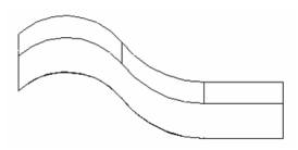
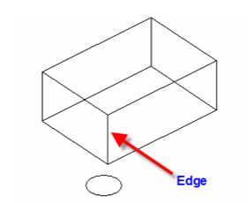
Use Edge as Path: When this option is ON you can use the edge of a 3D object as a path. You cannot use this option with a compound profile.
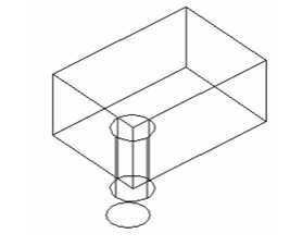
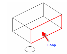
Use Loop as Path: When this option is on you can use the Loop of a 3D object as a path. A loop is all of the edges which enclose a single face of a 3D object You have to select the 3D object first, then its face. You cannot use this option with a compound profile.
Note: If you are trying to sweep by using a block as the path, you must have the Compound Path option turned on.
Sweep Shape Properties
The Properties window of an sweep object contains a Sweep Shape page, in which you can set geometric parameters.
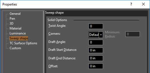
For these parameters to be accessible, the sweep must be created as a solid.
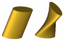
Twist Angle: The angle by which the sweep is twisted along the path.
Corners: Defines how the joints of multi-segmented extrusions will be formed. Default: Sharp corners.
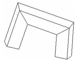
Bend: the rounding will be minimal.
If you want a larger rounding radius, specify a Minimum Radius.
Crimp: Keeps internal corners sharp, performs a minimal rounding on external corners.
Draft Angle: Creates an extrusion of increasing or decreasing cross-section. Enter the angle of deviation from the extrusion path.

Draft Start / End Distance: If Draft Angle = 0, you can specify a draft angle by entering the offset distances. Sweep does not allow you to create a TC Surface.
Tweak Face
(Available only in Platinum)
Default UI Menu: Modify/Modify 3D Objects/Tweak Face
Ribbon UI Menu:

Extends a 3D object by extruding selected faces to a selected 3D detination object. The reuslt is an ACIS Solid. The destination object must be a sheet body (ACIS Surface). ACIS surfaces/sheet bodies result when non-closed objects, such as a line segment, are extruded, revolved or swept. They can also be created from ACIS Solids by using the Create Solid from Surface tool, or by using the Create Surface from Profile tool on a closed 2D object, and by using the Extract Entity tool. Note: if the destination object is a closed volume, such as a sphere or closed revolve, thene the destination object will be solidified and added to the resulting tweaked object. To use the Tweak tool:
- Select the Tweak tool.
- Select the face of a 3D object.
- Select the 3D object to be the target of the extrusion.
- The result is a new 3D object.
Second Example:

 There are two options available with the Tweak tool:
- Leave source copy: If this option is on a copy of the original object being tweaked will be left in the model.
- Leave destination copy: If this option is on a copy of the destination object will be left in the model.
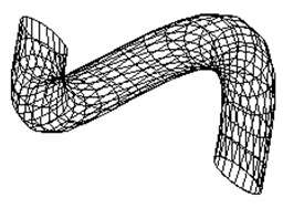
Twisted Extrude
(Available only in Platinum)
Default UI Menu: Draw/3D Object/3D Profile Based/Twisted Extrude
Ribbon UI Menu:
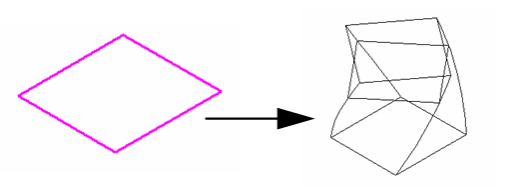
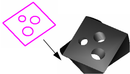
Creates a 3D object by extruding (sweeping) a 2D open or closed profile along a path normal to the workplane of the 2D object and imparting a twist. If you extrude an open profile, a surface will be created.
- If you want to select only a simple (single-object) curve, make sure Use Compound Profile is not selected.
- If you want to use a compound profile, which is a series of connected lines and/or arcs, select Use Compound Profile.

- If necessary, select Finish Selection of Profile to continue.
- Select the 2D open or closed profile to extrude. Move the mouse to extrude the profile, or enter a value in the Height field of the Inspector Bar.
If you select an open profile, the resultant object will be a surface.

If you select Two Sided Extrude, the solid extrusion will be created on either side of the profile.
Extruding Multiple Profiles You can also select multiple closed regions, or profiles, to extrude all at one time. Make sure Use Compound Profile is selected. Select the first profile, then press Shift to select additional profiles. Each profile is extruded the same distance.
If you select nested regions, you can create islands, and regions within islands.
Note: Compound profiles can be modified, which updates the 3D objects upon which they are based
Twisted ExtrudeShape Properties
The Properties window of an extrude object contains a Twisted Extrude Shape page, in which you can set parameters defining how the object is created.
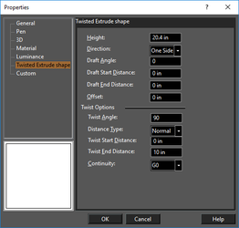
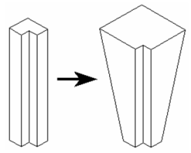
Height: The distance of the extrusion. Direction: Switch between one-sided and two-sided. For the following parameters to be accessible, the extrude must be created as a solid. Draft Angle: Creates an extrusion of increasing or decreasing cross-section. Enter the angle of deviation from the extrusion path.

Draft Start / End Distance: If Draft Angle = 0, you can specify a draft angle by entering the offset distances. Offset: Creates a hole in the extrusion at a distance from the outside of the extrusion equal to the Offset value.
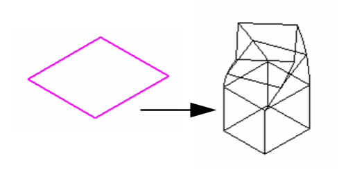
Twist Options
Twist Angle: Specifies the total rotation of the twist. Distance Type: Specifies where the twist will be applied to the extrusion. Normal applies the extrude between the Start and End distance. Full height applies the twist to the entire extrusion. Twist to Top applies the twist from the Start distance to the top of the extrusion. Twist Start Distance: Where the twist starts along the extrusion. Twist End Distance: Where the twist ends along the extrusion. Continuity: Specifies the smoothness of the transition between the straight sections and the twisted sections. G0 is the most abrupt transition, G1 is a more moderate transition, and G2 is the smoothest transition. For TC Surface Options, see TC Surface Properties