Facet Deform
(Available only in Platinum)
Default UI Menu: Modify/Modify 3D Objects/Facet Editing
Ribbon UI Menu:
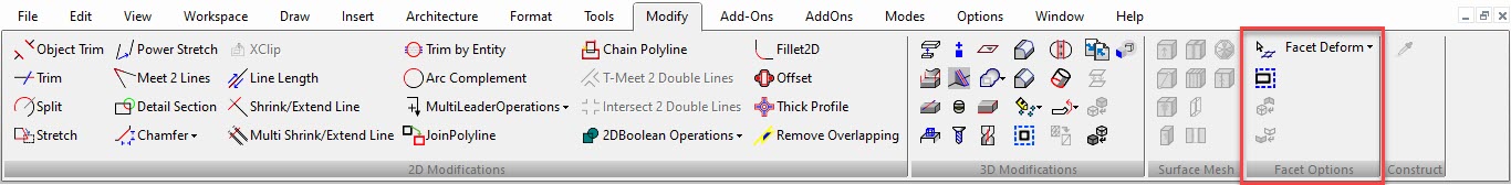
These functions enable you to change the shape of a surface or solid face by applying a uniform pressure, or by specifying deformation points and constraints. Facet Deform works only with ACIS solids and surface. It does not work on TurboCAD surface objects, objects that have TC Surface selected in the 3D page of the Properties.
Warning: Facet Deform causes the edited object to be deleted from the Part Tree. See Editing 3D Objects using Selection Info
Deform to Point

Default UI Menu: Modify/Modify 3D Objects/Facet Editing/Deform to Point
Ribbon UI Menu:
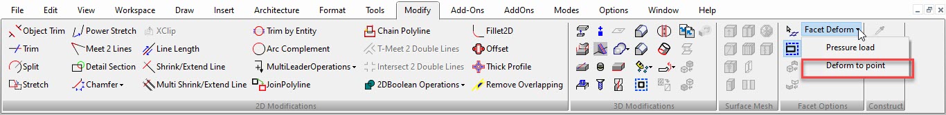
Enables you to deform a face or surface by moving one or more points on the face. The result is a NURBS surface or solid.
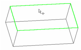
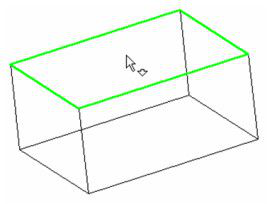
- Activate the Deform to Point function and select the face you want to deform - in this case, the top face of the box.
- The next step is to define deformation points and, if necessary, constraint points. You can click anywhere on the face to create points. If you created points in advance, use the Vertex snap to select them.
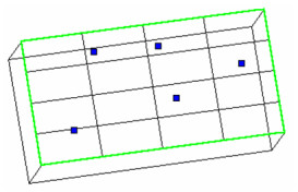
Any of these points that are not moved will be used as constraints; they will hold the face in place.
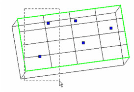
- Now select one or more points that will move. You can select points individually, or use a selection box.
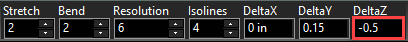
- Once points are selected, you can move them manually by dragging their reference point, or enter delta values in the Inspector Bar. In this example, the two selected points will move up in the Z direction.
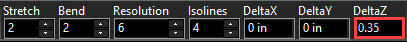
Note: For explanations of the other parameters (Stretch, Bend, etc.), see Pressure Load
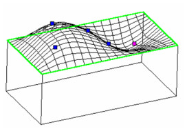
- Press Enter to move the points, and the face preview is updated. If necessary, you can now move other points. In this case, a single point is selected (rather than using a selection window).
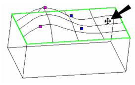
- This point will move in both Y and Z.
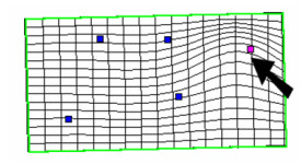
The preview now shows all three moved points. The two points that were not moved are used to hold the face in place. You can increase the number of isolines to better visualize the deformed face.
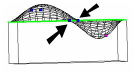
In this view, you can see the movement in Y of the single point shown.
And in this view, you can see the effect of the constraint points, those not selected to move.
Local menu options:
Note: For Linked neighboring faces and Fix Tangent, see Pressure Load
Delete constraint: Deletes the selected point or points. The deformation or constraint effect on the face will also be removed.
One Step Back: Use this if you want to change delta values for the points just moved.
Move Along Normal: Moves the points in a direction normal to the surface. In this case, you only need to specify a single Direction value.
Pressure Load

Default UI Menu: Modify/Modify 3D Objects/Facet Editing/Pressure Load
Ribbon UI Menu:
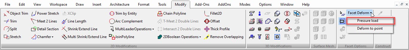
Enables you to deform a face or surface by applying a uniform pressure over the entire face. The pressure is always normal to the face. The result is a NURBS surface or solid.
- Activate the Pressure Load function, and set the pressure parameters (defined below).
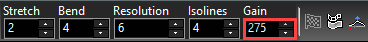
Stretch: A factor controlling elasticity - the resistance of the face to stretching. The higher the value the higher the resistance, resulting in less deformation.
Bend: A factor controlling the resistance of the face to bending (flexure) and torsion. Higher values prevent sharp changes to the face.
Resolution: The number of internal grids (knots) used to control the deformation. The higher the value, the greater the influence of Bend and Stretch factors. Lower values, however, yield faster results.
Isolines: Number of display lines. This does not affect the results, but is used to better visualize the deformed face.
Gain: The pressure value. A gain of 1,000 on a 10 x 10 face will have more of an effect than the same gain on a 100 x 100 face. Negative values can be used.
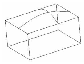
- Select the face or surface you want to deform. In this example, the pressure will be applied to the top face of a box.
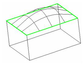
- A preview of the deformed face will appear, according to the parameters you set. You can adjust the values and press Enter to update the preview. If you need a better representation of the deformation, increase the number of isolines. A positive Gain value pushes the face up.
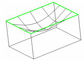
If you switch the Gain to a negative value, the face will be pushed inward.
- When you are satisfied with the deformation, select Finish from the local menu or Inspector Bar.
Local menu options:
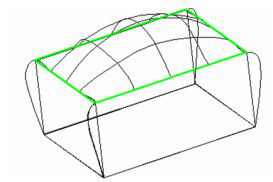
Linked neighboring faces: Adjacent faces will also be deformed.

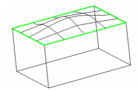
Fix tangent: Tangency at the face boundaries will be maintained. In this example, the face will remain horizontal along its boundaries.

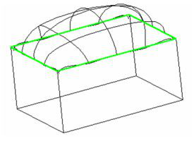
You can combine both local menu options to produce a deformation that is tangent to adjacent faces, with minimal deformation of the neighboring faces..

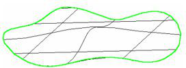
You can also deform a stand-alone surface such as this one, created by using Create Surface from Profile on a closed spline. (See Create Surface from Profile .)
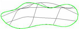
In this case, the local menu option Linked neighboring faces is not available. If you select Fix Tangent, the face remains horizontal along its boundary.