Parametric Parts
(Available in Platinum)
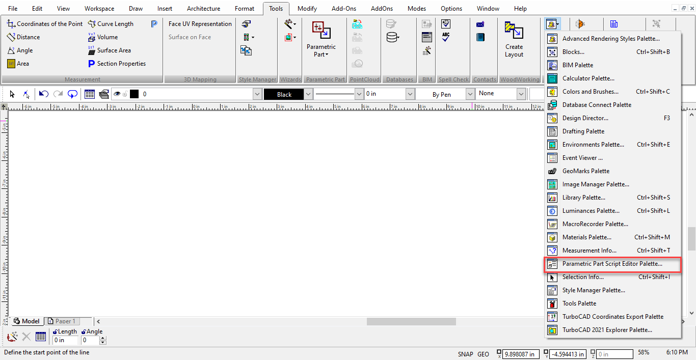
Default UI Menu: Tools/Parametric Part Manager, Tools/Palettes/Parametric Part Script Editor
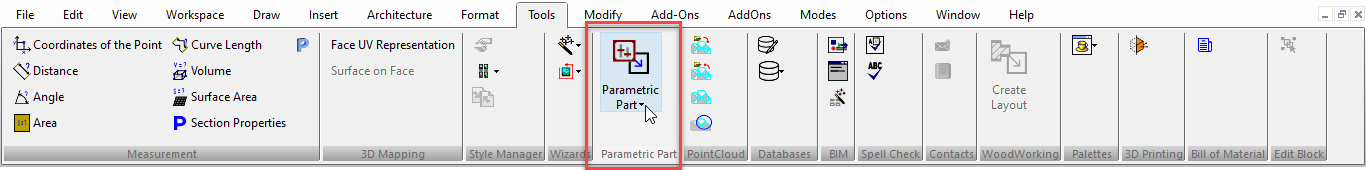
Ribbon UI Menu:
A parametric part is a group of objects that have parameters you can define before or after the part is inserted. For example, you can insert a bookcase whose height and shelf spacing can be defined.
Creating a Parametric Part
This section explains how to create a parametric part from within TurboCAD.
Note: You can also create a parametric part using a script. For details on creating scripts, check the "Docs" folder of the TurboCAD installation disk.
There are four basic steps in this process:
- creating the object(s) themselves
- saving the objects as a part and defining parameters
- defining relationships between parameters
- inserting the part
Step 1- Creating the Object(s)
In this example, a part will be created from a polyline with holes, made 3D by extruding it. The objects will be created using different sizes than the actual part that will be saved, to show that parameters can be used for accurate sizing.
- In this example, Auto Constraints is turned on. This is so that dimensions can be used as parameters, and so that geometric relationships between objects will be maintained when parameters are changed.
Note: For details on constraining objects, see Auto Constraint
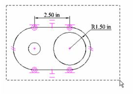
- Create a polyline using two identical linear segments and two tangent arc segments.
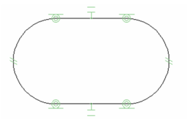
- Create two circles concentric with the polyline arcs. The circles can be different sizes now, but in the eventual parametric part, the circles will be identical.
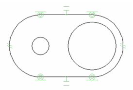
- Apply Concentric constraints so that the circles will remain concentric with the polyline arcs.
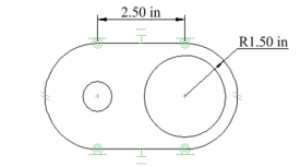
- Add a Linear Dimension and a Radial Dimension to measure the polyline.
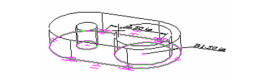
- Activate Simple Extrude, and make sure Use Compound Profile is active. Select the polyline, then press Shift and select two circles. Click to define the height, or enter an exact value.
Step 2- Defining the Part and its Parameters
Now a part will be created from this object. There will be five parameters defined for this part: H1 = radius of one internal circle H2 = radius of the other internal circle R = radius of the polyline arc W = length of the linear polyline segment D = extrude depth
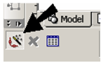
- Select Parametric Part Manager.
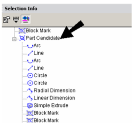
- Use a selection window to select all of the objects.
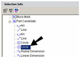
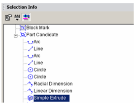
- The Selection Info palette opens, and the part is temporarily called "Part Candidate." Expand this item to see what the part contains.
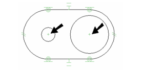
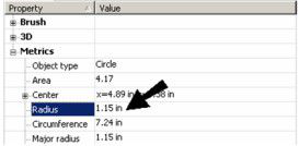
- The parameters H1 and H2 are for the two internal circles. Highlight the first Circle in the palette.
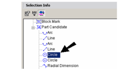
The circle is also highlighted on the model.
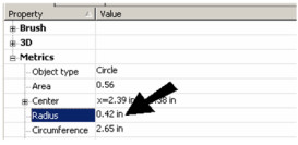
- The radius of this circle is found under "Metrics," at the bottom of the palette. Right-click on the Radius field.
-
-
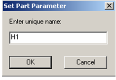
Enter the parameter name "H1," then click OK.
-
Note: You are not restricted to defining only geometric parameters. You can also define material, pen color, line width, etc. as parameters.
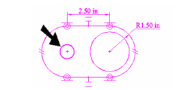
- Next, highlight the other Circle.
-
The other circle is now highlighted on the model.
-
-
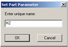
Right-click on the Radius field.
-
-
Enter the parameter name "H2."
-
-
For the next parameter, highlight the Radial Dimension.
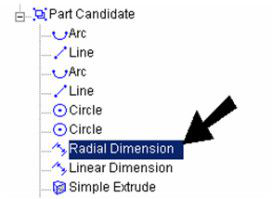
-
The dimension of the polyline arc is now highlighted.
-
-
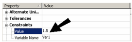
The Value field of this dimension is found under "Constraints." Right-click on this field.
-
-
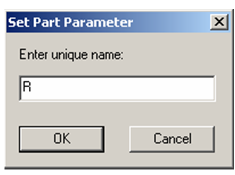
Name this parameter "R."
-
-
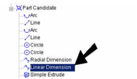
Next is the Linear Dimension.
-
-
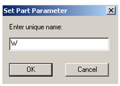
This value is also found under "Constraints." Name its parameter "W."
-
-
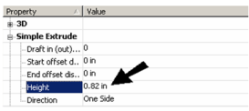
The last parameter is the depth of the part. Highlight "Simple Extrude."
-
-
This parameter is called "Height" and is found under "Simple Extrude." Right-click on this field.
-
-
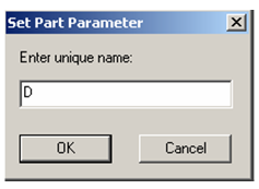
Name this last parameter "D."
-
18.Now that all five parameters are defined, select Finish from the local menu or Inspector Bar.
-
Note: There are other options in the local menu and Inspector Bar. Relocate Reference Point enables you to define the point by which the part will be inserted. For circular parts, Set Assembly Axis can be used to set an axis for assembly using Assemble by Axis (see Assemble by Axis).
Step 3- Defining Relationships between Parameters
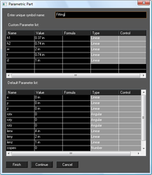
- The Parametric Part window is now open, in which you can define relationships between the parameters you've defined. First, enter a name for the part.
-
-
The eventual part will be defined by only three parameters: the hole radius, distance between hole centers, and depth. All other parameters will be functions of these three.
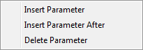
- The names of the parameters currently listed don't tell the user exactly what they are for, so we can add parameters with more obvious names. To do this, right-click on the first parameter on the list, and select Insert Parameter.
-
-
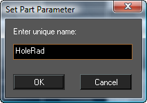
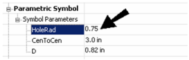
Name this parameter "HoleRad."
-
-
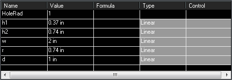
"HoleRad" is now first parameter on the list. Under "Value," enter the default radius that will be used when you first insert the part.
-
-
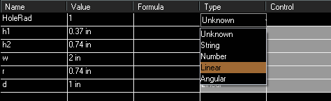
Under "Type," specify "Linear."
-
-
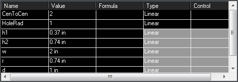
Create another parameter for the center-to-center distance between the holes. This parameter can be named "CenToCen". Specify an initial "Value" and "Type."
-
-
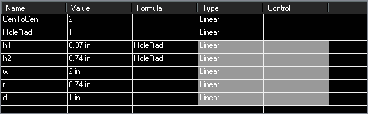
Under "Value" next to "H1," replace the number with "HoleRad." Do the same for "H2."
-
-
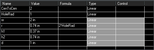
Define"R" as twice the hole radius.
-
-
Set "W" as equal to "CenToCen."
-
-
Now the three controling parameters needed for the part are defined. They are "HoleRad," "CenToCen," and "D." Click Finish to close the Parametric Part window.
Step 4- Inserting the Part
- Continue in the file in which you defined the part. Select Draw / Parametric Part. Select the part you just defined.
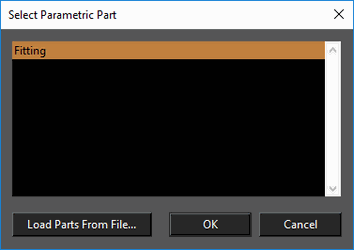
-
You may get a warning:
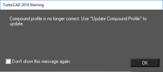
-
If you don't. want to see the message again , check the "Don't show this message again." box. Then click OK.
Note: Load from File can be used to insert parametric parts saved in other files.
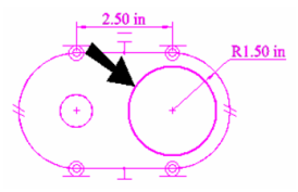
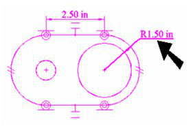
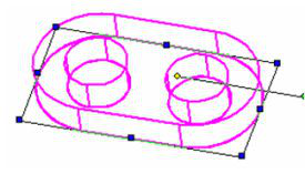
- Click to insert the part. The inserted part is shown to the right of the original geometry. Note that the two holes are equal, and that the polyline arc's radius is twice as large as the hole radius.
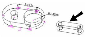
-
-
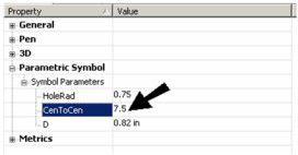
Select the part, and it appears in the Selection Info palette, with its three parameters available for editing. The initial values are the ones you set in the Parametric Part window.
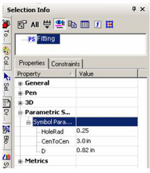
-
-
Increase "HoleRad."
-
The internal holes updates, as well as the overall radius of the part, which was set to be twice as large as the hole radius. In some instances you may get a warning message "Compound Profile is not up-to-date" when inserting the part.
-
-
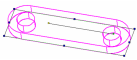
Increase the "CenToCen" parameter value.
-
The distance between holes updates, while the radius values remain the same.
-
-
The last value to change is "D."
-
This changes the depth of the extruded part.
-
Editing a Parametric Symbol
-
With the edit tool active you can save all of the Parametric parts in a *.SLW file.
-
You can also Load Parametric parts from an .TCW file. To Edit an exiting part. Click the local menu option Edit Existing Symbol*. You can edit either the content or the parameters. Content is the physical geometry. When finished, click OK and the part is saved with the changes.
Inserting a Parametric Part from the Library
The parametric parts included in the TurboCAD installation were created using scripts. (If you want to view these scripts.
Note: For details on how to save and insert parametric parts you create yourself.
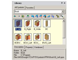
- For an example of a parametric part, open the "Books" category. Click on one of the parts, and the Description tab at the bottom shows the name and location of the part's file.
-
-
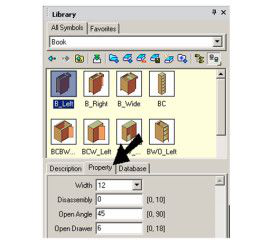
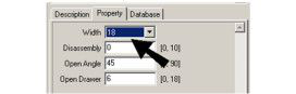
Open the Property tab. These are the editable fields defined in the part's script.
-
-
The properties with a drop-down arrow contain a list of pre-set, selectable values.
-
-
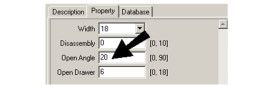
Fields that are not pre-set have a defined range of values you can enter. For example, Open Angle below must be between 0 and 90.
-
-
There are three ways to insert a part. You can click and drag the part from the palette to the drawing. Or you can double-click the part thumbnail. Or you can click the Insert Symbol icon. The part is inserted with the properties set in the palette.
-
-
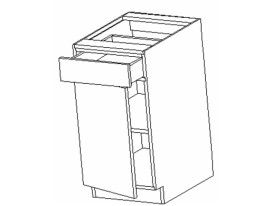
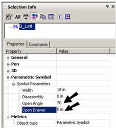
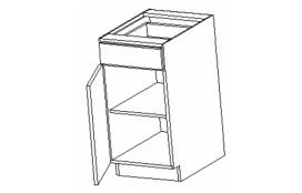
You can make changes to the part in the Selection Info palette. This palette shows the part's name, as well as fields for each of the properties shown in the Library palette. In this example, Open Angle was increased to 70 degrees, and Open Drawer was changed to zero.
-
Now the drawer is closed, and the door is open wider.
-
Loading a Parametric Part into the Library
This section explains how to save, and then insert, a parametric part created within TurboCAD. For details on creating parametric parts, see Creating a Parametric Part
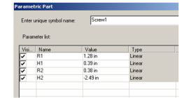
- In this example, two cylinders are used to create a parametric part representing a simplified screw.

-
-
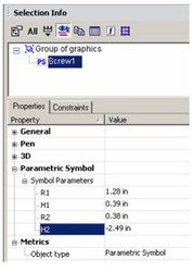
Use Parametric PartManager to create a part from these two objects. There are four parameters defined: radius and height for both cylinders
-
-
When the part definition is completed, erase all objects in the drawing.
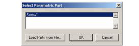
- Select Parametric Part to insert the screw.
-
The part, and nothing else, is now in the drawing.

-
-
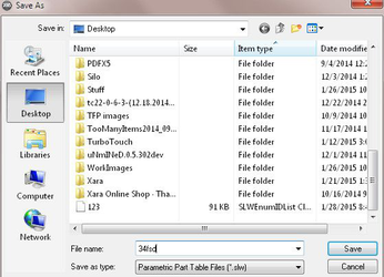
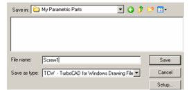
Now the file can be saved. In this example, the file is saved as "Screw1.tcw" in the folder "My Parametric Parts."
-
-
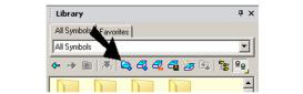
Start a new file, and open the Library palette. To load the new folder, click Load Folder.
-
-
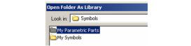
Browse to the "My Parametric Parts" folder and load it.
-
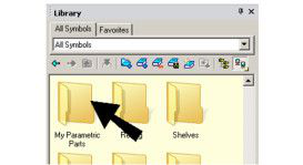
The folder now appears in the library.
-
-
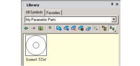
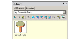
Open "My Parametric Parts" to see the "Screw1" part.
-
-
Right-click on the thumbnail and update it, if you want.
-
-
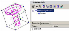
Drag the part from the library into the drawing. Open the Selection Info palette, and you can see that the part is a group.
-
-
To edit the part, you can Explode it, or just highlight its name in the palette and edit its parameters.
-
Note: If you add more parts to the same folder, they will not automatically appear in the library. You need to use Unload Library to remove the folder, then use Load Folder to load it again.
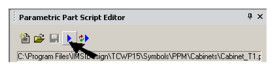
Parametric Part Script Editor
Default UI Menu: Tools/Palettes/Parametric Part Script Editor
Ribbon UI Menu:
Other than creating a parametric part from within TurboCAD, the other way to create a part is to write a script. The parts provided in folders such as "Cabinet" are created this way. For details on creating scripts. If you want to write your own script, or edit an existing script, you can use the Parametric Part Script Editor.
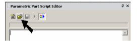
- To load an existing script into the editor, click Open.
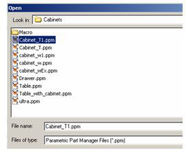
- Locate one of the scripts in the "Cabinet" folder.
- The script appears in the editor.
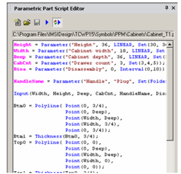
Note:Scripts can be edited in any text editor as well.
- A scripted part can be loaded into the drawing by clicking Insert PPM Symbol.