Assembling
Default UI Menu: Modify/Modify 3D Objects/3D Assemble
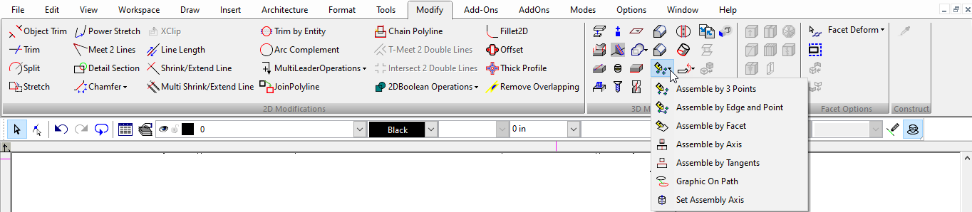
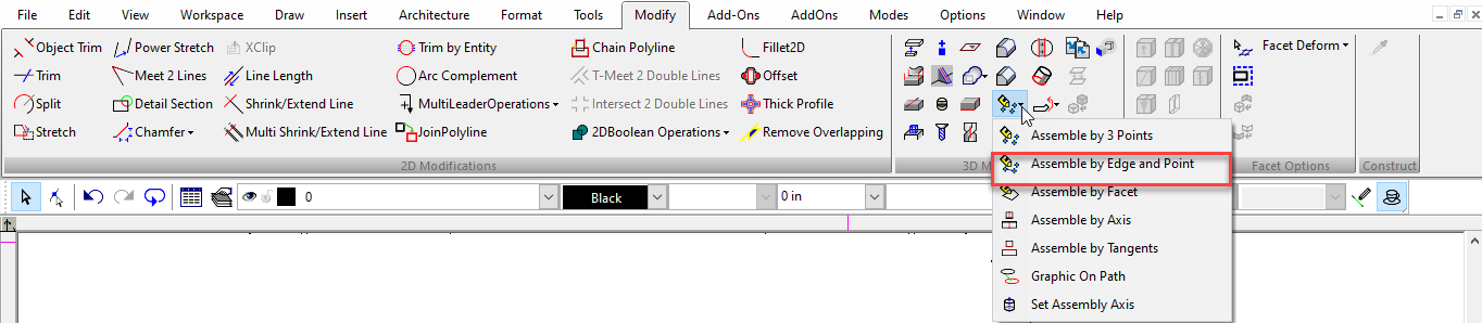
Ribbon UI Menu:
The Assemble tools are used to position a 2D or 3D object relative to another object.
The Assemble tools can be used on 2D and 3D objects. For the objects you want to use, be sure the Selector is set correctly (2D, 3D, or both). See 2D-3D Selector. These tools are available on the 3D Modify toolbar, which you can display by right-clicking in any toolbar area and selecting 3D Modify. 
Note: The Transform tools also enable you to move objects, as well as scale and copy, and do not require information as accurate as that required by the Assemble tools. In addition, you can record Transform operations for use on other objects. See Transforming
Assemble by 3 Points

(Available in Platinum, Professional and Deluxe)
Default UI Menu: Modify/Modify 3D Objects/3D Assemble/Assemble by 3 Points
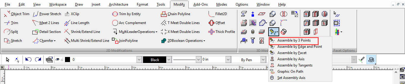
Ribbon UI Menu:
Changes the position of an object by changing the location of one point, two points (line), or three points (plane). The source points typically lie on the object to be moved, although this is not required. Destination points can lie on destination objects, or they can be specified in the Coordinate Fields. To assemble by one point:
- Select the object to be repositioned.
- Select the source point.
- Select the destination point.
- Select Finish from the local menu or Inspector Bar. The object is moved so that its source point meets the destination point, keeping its orientation.
To assemble by two points (line):
- Select the object to be repositioned.
- Select the first source point and its destination. This first set of points determines the actual object position; the remaining points set the orientation.
- Select the second source point and its destination.
- Select Finish from the local menu or Inspector Bar. The object is moved so that its first source point meets the first destination point, and the line between source points becomes aligned with the line between destination points.
Note: For another way to assemble by edges, see Assemble by Edge and Point.
To assemble by three points (plane):
- Select the object to be repositioned.
- Select the first source point and its destination. This first set of points determines the actual object position; the remaining points set the orientation.
- Select the second source point and its destination.
- Select the third source point and its destination.
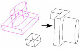
The object is moved so that its first source point meets the first destination point, and the plane defined by the source points becomes aligned with the plane defined by the destination points.
Note: In a particular case, just after two clicks "finish" is enabled in local menu. But in common case you can repeat 2 point selection 3 times: 6 clicks. So you can achieve any position of the object in space
Assemble by Edge and Point

(Available in Platinum, Pofessional and Deluxe)
Default UI Menu: Modify/Modify 3D Objects/3D Assemble/Assemble by Edge and Point
Ribbon UI Menu:
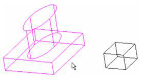
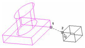
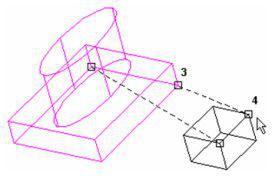
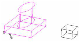
Changes the position of an object by changing the location and alignment of an edge. You can also add a source point and destination point to change the rotation as well. To assemble by a pair of edges:
- Select the object to be repositioned.
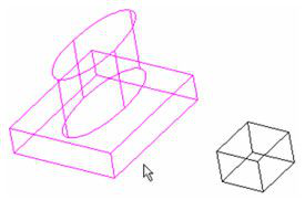
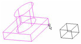
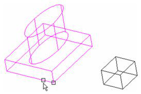
- Select the source edge. The new alignment of the edge depends on where you select the edge; the point you select will be moved to the point you select on the destination edge.
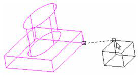
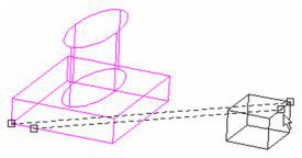
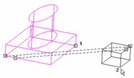
- Select the destination edge. The dotted lines indicate how the object will be aligned.
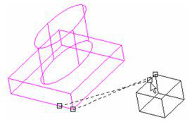
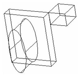
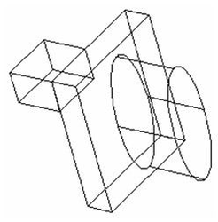
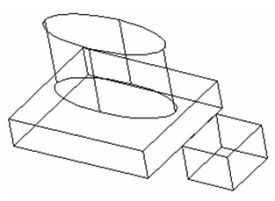
- Select Finish from the local menu or Inspector Bar. The object is moved so that its source edge meets the destination edge, connected at the two selected points.
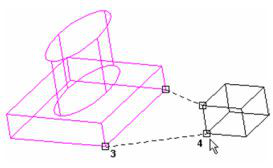
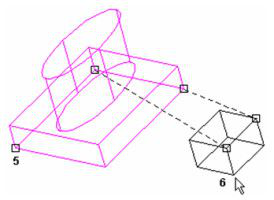
To assemble by edges and a plane:
- Select the object to be repositioned.
- Select the source edge. The new alignment of the edge depends on where you select the edge; the point you select will be moved to the point you select on the destination edge.
- Select the destination edge. The dotted lines indicate how the object will be aligned.
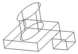
- Select a point on the source plane (not on the selected edge) and a point on the destination plane.
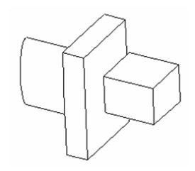
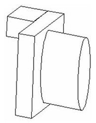
The object is moved so that its source edge meets the destination edge, connected at the two selected points. The rotation is set by the points on the source and destination planes. The results are shown here in Hidden Line render mode.
Assemble by Facet
(Available in Platinum, Professional and Deluxe)
Default UI Menu: Modify/Modify 3D Objects/3D Assemble/Assemble by Facet
Ribbon UI Menu:
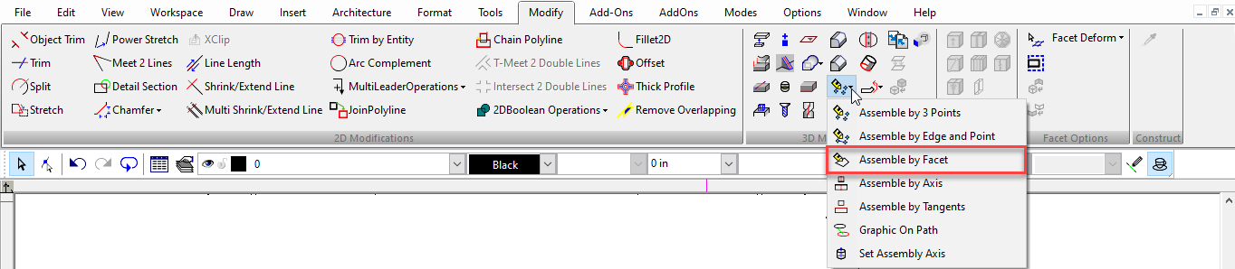
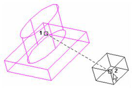
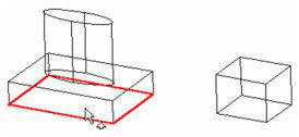
Changes the position of an object by aligning facets.
- Select the source facet of the object to be repositioned. To select a facet behind or in front of the indicated facet, you can use the Page Up and Page Down keys.
 |
|
- Select the destination facet.
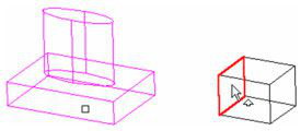
The object is moved so that the source facet meets the destination facet. The results are shown here in Hidden Line render mode.