Blocks
Blocks
(Available in all TurboCAD Variants)
One or more objects can be combined and stored as a block. A block is treated as a single object for purposes of selecting and editing. Each block is stored in the drawing's internal library, and each instance of the block is a reference to this source. This means that numerous instances of a block can be added to the model without significantly increasing the file size. Groups are similar, but they are not linked to sources; each group contains its own drawing data.
Note: A drawing's block library is internal to the drawing, and is stored with the file. Symbol libraries are similar but are stored separately, and can be accessed while in any drawing. If you need to create a group of objects that will be used in multiple drawings, create a symbol.If you want to import the entire contents of another file (TurboCAD or other format) as a block.
Because blocks can contain individual objects, groups, and other blocks, they can be complex hierarchical structures. For block manipulation, use the Blocks Palette (View / Blocks).
Tip: You can use the TC Explorer Palette to view blocks of any open drawing, and to drag blocks to and from drawings.
You will find details on using block and the Blocks palette on the following pages:
Additional Block Controls

Show Selected: Toggles the Show Selection option. When on the result will be that anytime a single block is selected int the drawing space, that block will be selected and highlighted in the Blocks palette.

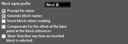
Block name prefix: If names are automatically generated, you can enter a string that appears before the item name. The "@" character is a placeholder for the automatic number. Prompt for name: You will receive a prompt each time a new item is created. Generate block names: Names will be automatically assigned. Insert blocks when creating: Each block will be inserted into the drawing once it is created. Compensate for the offset of the base point at the block references: Prevents updating of the reference points for inserted blocks, when a the block reference point is relocated. Show Selection any time an inserted block is selected: Toggles the Show Selection option. When on the result will be that anytime a single block is selected int the drawing space, that block will be selected and highlighted in the Blocks palette.
Block Attributes

Default UI Menu: Draw/Block/Block Attributes
Ribbon UI Menu:
A block attribute is AutoCAD- informational text associated with a block, that you can enter whenever you insert a block. TurboCAD reads and displays block attributes from AutoCAD drawings (DWG) and DXF files.
- Create the objects that comprise the blocks.
(You can also add a block attribute after a block has been created, in Edit mode. This is done the same way as adding another geometric object.
- Select Block Attribute Definition. Select the start point for the text, preferably on or near the block objects.
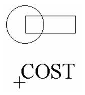
- Type the "tag" name for the block attribute, such as "COST." This name is used to uniquely identify the attribute within the block, since more than one attribute can be created. If the rawing will be sent to AutoCAD, do not use spaces (use underscores instead).
Note: This tool works like the text tool, in terms of alignment and local menu options.
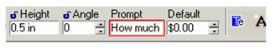
- Enter the prompt and default value in the Inspector Bar, or you can enter these properties later. For example, the Prompt can be "How much does it cost?" and Default can be $0.00.
- Press Enter to finish the definition. You can create multiple attributes, such as Part Number, Owner, etc.
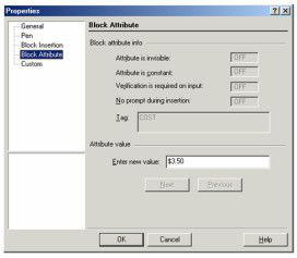
Once the block attribute is created, you can open its Properties to add or change the Tag, Prompt and Default values, as well as Mode.
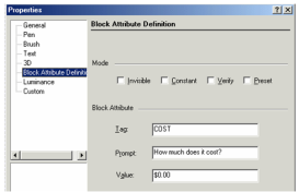
Mode: Affects how the dialog appears when the block is inserted: Invisible: The text of the block attribute is not displayed in the drawing. You can see the information in the Selection Info Palette or edit it by displaying the block's properties.
Warning: When you explode a block containing invisible block attributes, the information is lost.
Constant: The attribute value is fixed and unchangeable. It is shown to you during block insertion. Exploding the block will turn the block attribute into text that can then be edited. Verify: Prompts you to verify that the attribute value is correct when you insert the block. In AutoCAD, the attribute value is shown for your verification during block insertion if the AutoCAD variable ATTDIA is set to 0. This flag has no effect in TurboCAD as it takes place in AutoCAD when the variable ATTDIA is set to 1. Preset: Sets the attribute to its default value when you insert a block containing a preset attribute. In AutoCAD, you are not prompted for a value if the AutoCAD variable ATTDIA is set to 0. This flag has no effect in TurboCAD as it takes place in AutoCAD when the variable ATTDIA is set to 1. When the block attributes are defined, simply include them in the selection of objects that will make up the new block.
Setting Block Attributes
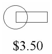
When you insert a block that has one or more attributes, a window will appear that gives the prompt and offers the default value. For example, the prompt says "What does it cost?" the default value is $0.00. The value can be changed to another value, in this case, $3.50.
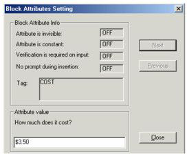
For multiple attributes, use the Next and Previous buttons to set values for all of them. When the block is inserted, the value is included with the objects.
When a block has attributes defined, its Properties will contain an additional page - Block Attribute. You can edit each attribute value in this window, using the Next and Previous buttons to scroll through multiple attributes.
Sync Attributes
Sometimes it is necessary to add attributes to blocks after many instances of the blocks have already been inserted into the drawing. In this case the new attributes are not automatically added to the prior insertions. The Sync Attributes button will add the new attributes to the older blocks.
The values for these newly synced attributes within the older blocks will be the default value you assign to the attribute when you create it and it will blank if no value is assigned. For blank attributes you will have to select the existing blocks and assign values to those attributes.
Extracting Block Attributes
If you attach attributes to blocks, you can extract these attributes and display them in a table. You can also export the attributes to a report in an external file.
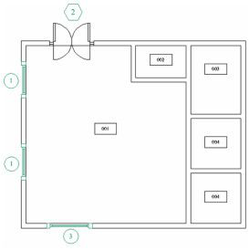
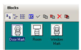
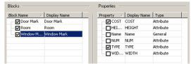
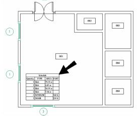
This example has three blocks used to mark windows, doors, and slabs.
Here are the three blocks in the Blocks Palette.
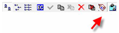
- Select Extract Attributes. In this window you can select the blocks and attributes that will be included in the schedule or report.
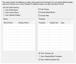
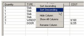
Note: You can re-order a a column by dragging its header to the new location. Scan Entire Drawing: Attributes will be extracted from all paper spaces and model space.
Scan Model Space: Attributes will only be extracted from model space.
Scan Current Space: Attributes will be extracted from the current model space or paper space.
Scan Selected Entities: Attributes will be extracted only from currently selected objects.
Scan Groups: If any groups contain blocks, these blocks will be scanned for attributes.
Scan Nested Block: If blocks contain nested blocks, these nested blocks will be scanned for attributes.
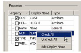
Include Xrefs: The content of Xrefs will also be scanned. The Blocks list contains all blocks that have attribute definitions. The Properties list all attributes found for the blocks checked in the Blocks list.
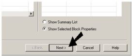
Show Summary List: The Properties list contains all attributes for all blocks checked in the Blocks list.
Show Selected Block Properties: The Properties list contains attributes only for the block that is currently checked in the Blocks list.
Show Visible Properties Only: If selected only attributes that are visible will be shown.
- You can select attributes for each block that will be included. For example, click Show Selected Block Properties at the bottom, and select the "Door Mark" block. Check only the "COST" and "TYPE" attributes.
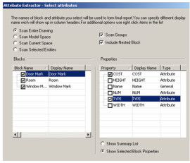
- Select the "Room" block and check "AREA," "COST," and "TYPE."
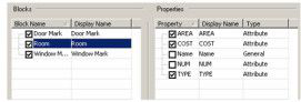
- Select the "Window Mark" block and check "COST" and "TYPE."
You can right-click on any field under Blocks or Properties to get a popup menu in which you can check or uncheck all, or change the display name.
- When the blocks and properties are defined, click Next.
TurboCAD scans the file, and the Preview window displays the results.
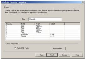
If TurboCAD Table is checked, the report will be inserted into the file. If you want to export the results, click External File. You can click on any column header to change the sorting order, or hide or rename a column.
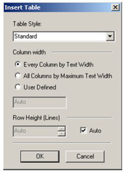
- Click Finish. If the table is to be inserted into TurboCAD, you will see the Insert Table window. Here you can define the column and row sizes.
- Click OK, and then click where you want to place the table.
You can make changes to the table formatting in the Selection Info palette.
Creating a Block

Default UI Menu: Draw/Block/Create Block
Ribbon UI Menu:
Combines all selected objects into a block. Objects can include drawing objects, images, OLE objects, groups, and other blocks. Blocks can be comprised of 2D and 3D objects.
Warning: You should move all objects to be used in a block to Layer 0, before creating the block. Many features will not work properly otherwise.
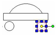
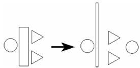
- Create the objects you want to combine into a block. Each object is separate, as you can see in Select mode.
You can set the reference point of the objects before creating the block or you can change it later.
- Select the objects you want to include in the block.
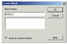
- Click Create Block.
- If auto-naming is not used, you must assign the block name. Check Insert at current location to create the block in place. Otherwise, the block will be removed from the drawing and stored in the library for future insertion.
- The block is created. If the block is inserted in the drawing, you can select it as one object.
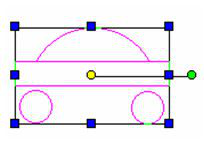
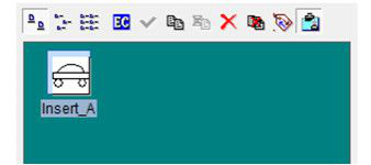
Blocks are created on Layer 0, even if their components are on other layers. To insert the block. If you open the Blocks Palette, you can see each block you have created. You can also add blocks to the drawing, edit blocks and create new blocks using this palette.
Warning: Do not include lights in a block. If you do, the lights will remain in their original locations regardless of where you place the block in your drawing.
Creating a Block by Drag and Drop
To create a block this way, the Blocks Palette must be open. Select Blocks palette, or the Blocks Palette tab.
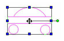
- Select the objects that you want to combine into a block. Click and hold the reference point (the yellow circle). The cursor turns into a double arrow.
- Drag the objects into the Blocks Palette. If auto-naming is not used, assign a block name.
- The block appears in the Blocks Palette.
Editing a Block
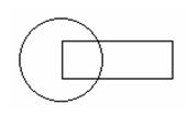
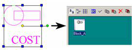
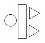
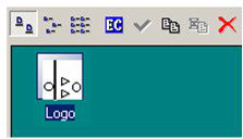
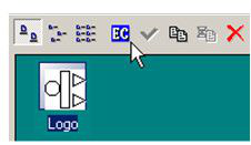
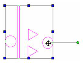
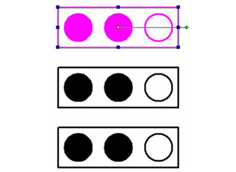
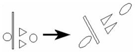
(Changing a block's contents) You can use any editing or node editing tool to modify, move, copy, add, etc. objects that comprise a block. This example use the block shown below, consisting of four objects. The block name is "Logo."
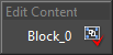
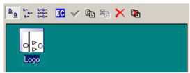
- In the Blocks Palette, select the block, and click Edit Content.
- In edit mode, the screen contains only the block components, which are available for editing. You can add, delete, or edit objects. Whatever appears on the screen will become part of the edited block.
- When finished, right click and select Finish block/group editing, or click Finish Edit Content in the Blocks Palette.
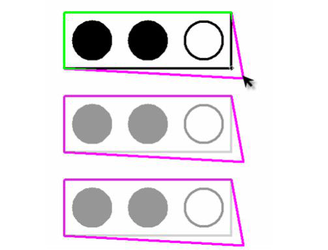
The icon for the block is updated to reflect the edited components. Any instances of the block already in the drawing are updated, including resized and scaled blocks.
when a block is edited, an editing mode indicator bar is displayed.
When block editing is done, click "Finish to Edit Block" in the indicator bar.
Relocating a Block Reference Point
Hotkey: Ctrl+Shift+R
A block is inserted by placing its reference point. By default, the reference point is at the center of extents of the entire block, but this location can be changed.
- In the Blocks Palette, select the block, and click Edit Content.
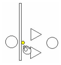
- Activate Relocate Block Ref Point. The default reference point appears, as a yellow circle.
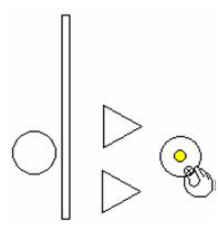
- Click to specify the new location for the reference point.
- Select Finish to Edit Block, or click Finish Edit Content in the Blocks Palette.
Now when you insert the block by dragging, you will drag it by the new reference point.
Note: For any instance of a block you can move its reference point and rotation bar. However, this change only affects the block itself and any copies of it. New instances of the block will use the block's defined reference point.
Changing a Block Name and Description
- To change a block name or add a description, double-click the block icon in the Blocks Palette.
- Make the necessary changes in the Edit Block window.
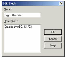
- After the changes are made, any description you add will be displayed as a tool tip on the block icon.
Copying a Block
This section is on copying a block to create a new block. To create copies of the same block in the drawing, you can use any of the standard editing tools.
- To copy a block, select it in the Blocks Palette and click Copy.
- Depending on the Auto-Naming settings, a copy will be created with a generated name, or you will be prompted for a name.
- The new block appears in the Blocks Palette, and can be edited like any other block.
Deleting a Block
Press Delete a Block button. Remove block with all references: Deletes the block and all instances. Be careful when using this option, because it cannot be undone.
Replacing Blocks
One convenient feature of blocks is that they can easily be replaced by other blocks. You can replace all blocks in the drawing, or just selected blocks.
- To replace instances of a block, select the block in the Blocks Palette and click Replace References.
- In the Replace Block Reference window, select the replacement block. You can also choose to replace all instances in the entire drawing, or just those in the active space (visible).
- Click OK to implement the change.
To replace an instance of a single block, open its Properties to the Block Insertion page. Use the Replace with button to replace it with another block.
Exploding a Block
Click the Explode icon.
If you explode a block that contains nested groups or blocks, the nested groups will remain intact. Each sub-block must be exploded separately.
External References
Default UI Menu: Insert/Create External Reference
Ribbon UI Menu:
An external reference (xref) is a kind of a block in that it is stored in the current drawing's block library. However, unlike a block, the objects associated with an xref definition are not stored in the current drawing; they are stored in another drawing file. When you create an xref, the entire contents of this other file are imported as a block.
Note: You can also access An external reference via Block palette.
Xrefs are usually used to display the geometry of a common base drawing in the current drawing, such as a frame. They can be taken from files any formats readable by TurboCAD. Only files that have objects in Model Space can be added as Xref's.
- To import another drawing as a block (xref), select Insert / Create External Reference.
- In the External Reference File Location window, select a file type and locate the desired file.
- The selected file is added to the block library of the current file. You can view it and insert it using the Blocks Palette. However, you cannot edit an xref in the Blocks Palette - you must change the original file.
Note: If you edit the original file from which the xref was created, the block in the current library will not change. You will need to recreate the xref.
External References Panel
If you click on the External References button at the top of the Block palette you will see the External References panel at the bottom of the palette. 
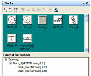
When xref's are nested in other drawings they are shown in a tree format listed below that referenced drawing. Right-clicking on any of the xrefs listed in the external References panel will open the following local menu:
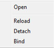
Open: will open the xref in TurboCAD. Reload: will reload the reference file, including any updates. Detach: will detach the referenced file, and any insertions of that file in the drawing will be deleted. You cannot detach nested xrefs. You must open the file to which they are attached to remove them. Bind: embeds the selected XREF as a Block in the drawing. All attachment to the external drawing is lost. VISRETAIN:Through the Design Director it is possible to edit the various properties of the layers within an XREF. These changes do not affect the original drawing. Even if the external referenced drawing is altered these layer changes will be retained. However, if the XREF is reloaded the changes will be lost. It is possible to disable this feature by changing the $VIZRETAIN variable through the DCExplorer Palette. Exploding XREFs: When an XREF has been bound to a drawing it becomes a block. Instances of that block in the drawing can be exploded so that you can edit the geometry directly in the drawing.
Automatic Updating of Xrefs
When using a file with Xrefs, if any of those external files are updated, TurboCAD will prompt you if you want to regenerate the file with the updated Xref(s).
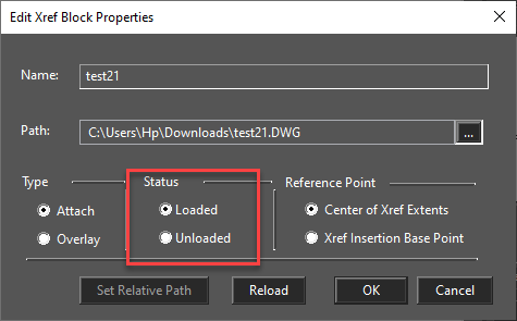
Editing Xrefs Block Properties:
Editing Xref Blocks is similar to editing other blocks. The only difference is that Xref blocks have an option "Status", with two values: “Loaded” and “Unloaded” has been added to the Edit Xrefs dialog box. When a referenced drawing (Xref) is Unloaded from the current drawing, the drawing opens much faster and uses less memory. When the Xref definition is unloaded from the drawing file, the internal pointer to the referenced drawing remains. You can therefore restore all the information by Loading the Xref. In order to maximize the performance of TurboCAD, it is recommended that you Unload any referenced files if they are not needed in the current drawing session but may be used later for printing/plotting.
In Place Editing of Groups and Blocks
You can edit groups or blocks in place within the drawing.
- Select the block or group.
- Right click to open the local menu and select Edit tool.All other elements in the drawing will fade-out, while the selected entity remains clear.
- Proceed by making you desired changes to the object.This can include changing properties, moving geometry, adding geometry, editing geometry, and deleting geometry.
- If you are editing a block, other instances of the block will show the changes you are making simultaneously.
- To finish, right click and select Finish block/group editing, from the local menu, or Finish Edit Content from the Block Palette toolbar, or Finish to Edit Block/Finish to Edit Group form the Tools menu.
Block attributes that are edited, added or deleted will not be updated in exiting block insertions, including the one that you selected. Only the "Original" block in the palette will reflect attribute changes. As of TurboCAD latest version, you can now snap to objects outside the block or group while in block/group mode.
Inserting a Block
To insert a block into the drawing, simply drag it out of the Blocks Palette and drop it into your drawing. The inserted block will still be selected after you place it, so that you can move, scale, or rotate it. Blocks are placed on Layer 0, even if their components are on other layers. Layer 0 should always be left visible, or blocks will instantly "disappear."
Tip: You can use the TC Explorer Palette to drag blocks to and from drawing.
The Selection Info palette shows the Block Insertion structure. This feature does not allow the editing, but only visualizing the structure.
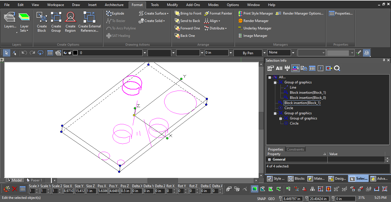
Block Insertion Properties
These properties can be used if you want to change any aspect of the block instance - its location, scale, angle, or the block reference itself. For any block, open the Properties window and open the Block Insertion page. For example, a block was inserted, then moved, rotated, and resized.
Its Block Insertion page contains the current values for Position, Rotation, and Scale.
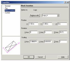
You can change the values in this window, or use the Select Edit tools and see the updated values in these fields. To replace a selected block with another block, select the replacement block from the list and click Replace with. Click OK to implement the change.
Inserting Blocks into Another File or Application
You can also use the drag-and-drop technique to insert blocks into another open file. Dragging a block into another drawing accomplishes two things: it inserts the block into the target drawing, and it places the block into the library of the target document. The target drawing must be open and its window must be visible on the screen. (Use Window / Tile to see all open windows.) After you drag the block, the target file becomes the active window. Drag-and-drop can also be used to place blocks, symbols, or any selected objects into other Windows applications, such as Microsoft Word or graphics programs.
Note: You can also use File / Extract To to export all blocks into another file.
Inserting Blocks from Another File
The Insert / File tool can be used to insert some or all blocks from another file into the current drawing . If both drawing have blocks with identical names, you can choose whether to ignore or replace them.
Tip: You can also use File / Extract From to insert selected components like blocks (or layers or other settings) from another file into your drawing. However, this method will insert all blocks, without enabling you to pick and choose.
- Select Auto Naming and make sure that Prompt for Name is checked for Blocks.
- Select Insert / File and choose a file containing one or more blocks you wish to insert.
- Use the Add Blocks window to select the blocks to import:
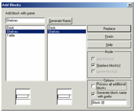
The left panel displays the blocks found in the selected file, and the right panel displays any blocks that exist in the current drawing. Select the mode (Add, Replace, or Ignore) and click the relevant button at the top right (Add, Add / Replace All, etc.) to generate the blocks. If you want to pick and choose the blocks to add, make sure Process all additional blocks is not checked. Generate name: Assigns a new name to a block you wish to add. Modes: The options here depend on the selected block, and whether a block with the same name already exists in the current drawing. Add block(s): Adds the selected block. Replace block(s): The blocks from the external file will replace those in the current drawing. Ignore block(s): Click Ignore All and the blocks will not be added.
Options
Process all additional blocks: Adds and/or replaces all blocks found in the source file. Generate block name with prefix: Assigns a name automatically, with the specified prefix, to the inserted blocks. Using Insert / File also adds all drawing objects found in the source file. However, you can press Undo (Ctrl+Z) immediately after using AddBlocks to clear the imported objects, leaving only the imported blocks. You may have to undo twice, to remove objects both in Model Space and Paper Space. Other source file components like layers, lights, and views will also be inserted, but they can be deleted manually if needed.
Warning: If the source file and current drawing have layers or other components with identical names, the layers will be replaced with those of the inserted file.
There are other ways to import blocks from another drawing, without importing other components: Open both the source file and new file, and select Windows / Tile so that you can see both drawing windows. Use the Blocks Palette to drag blocks from the source file to the new file. This method imports the blocks only. In the source file, select the blocks you want to export (select in the drawing area, not in the Blocks Palette). Copy the blocks (Ctrl+C or Edit / Copy), and paste them (Ctrl+V) into the destination file. The AddBlocks window will appear. This method imports both the blocks and the layers the blocks are on.