Coordinate System
(Available only in Platinum)
Default UI Menu: Modify/Modify 3D Objects/Create Surface, Modify/Modify 3D Objects/Create Solid
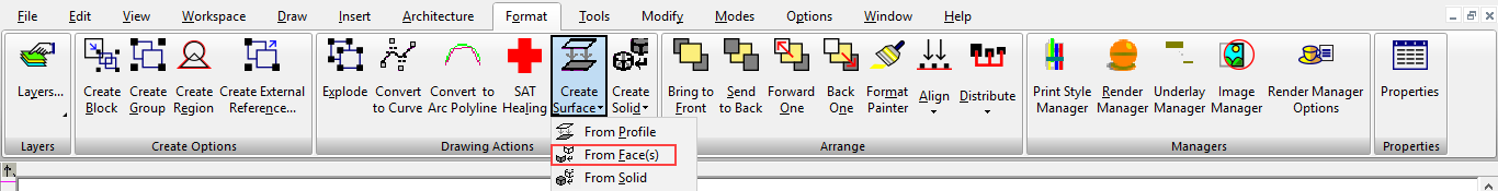
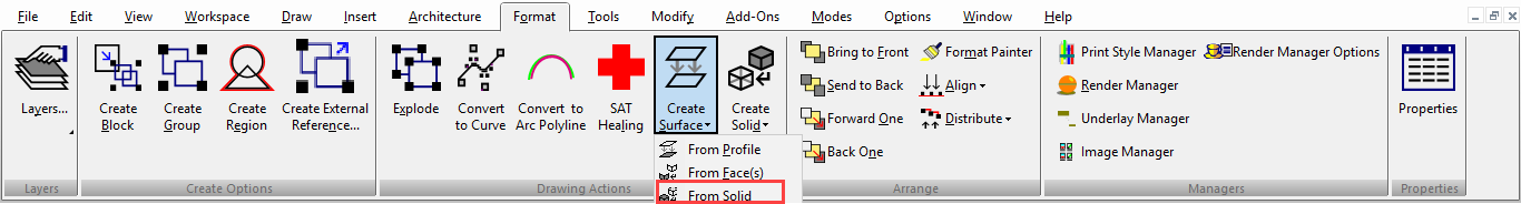
Ribbon UI Menu:
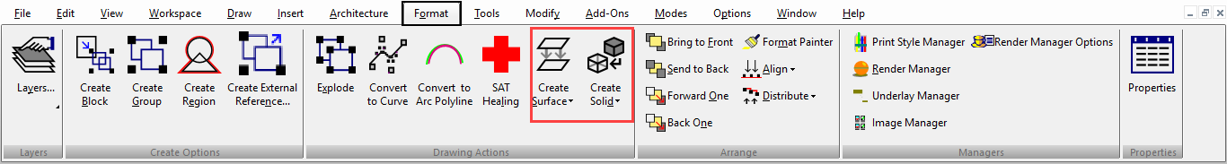
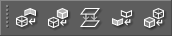
In TurboCAD, "surface" refers to a 3D ACIS object, whereas a TurboCAD surface (when TC Surface is checked in the 3D page of an object's Properties) refers to an object created with TurboCAD's internal engine, which is not an ACIS object. These are conversion operations that create surfaces or solids from existing objects, including surfaces, faces, and profiles. You can display the Solid/Surface toolbar by right-clicking in any toolbar area and selecting Solid/Surface.
Create Solid from Face(s)
Default UI Menu: Modify/Modify 3D Objects/Create Solid/From Face(s)
Ribbon UI Menu:
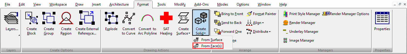
This tool works with ACIS objects only. It does not work with TC Surfaces. Enables you to convert one or more surfaces / faces into a solid. The faces must be contiguous, but they do not need to share boundaries over the entire boundary length.
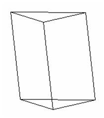
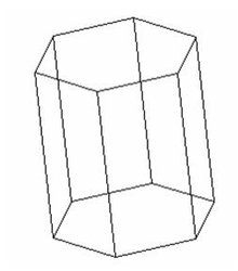
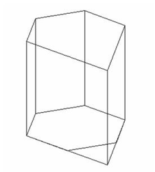
- Start with one or more solids. This example uses a 6-sided polygon extruded (using Simple Extrude) into a solid.

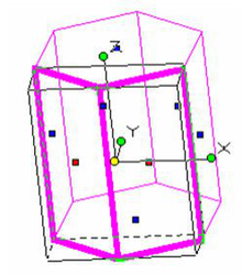
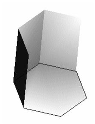
- Activate Facet Edit and select one or more faces. Use Shift to select multiple faces.
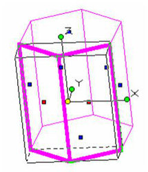
- Activate the Solid from Face(s) function, and the selected faces are now facets of a solid. Faces are added as needed to complete the solid.
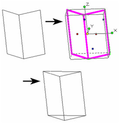
You do not have to start with a solid; this function also works with objects that are already surfaces.
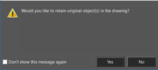
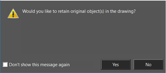
- You will be prompted as to whether you wish to retain the original object.
Create Solid from Surface
Default UI Menu: Modify/Modify 3D Objects/Create Solid/From Surface
Ribbon UI Menu:
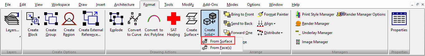
This tool works with ACIS objects only. It does not work with TCSurfaces. Enables you to convert a surface into a solid volume, within the surfaces' boundaries.
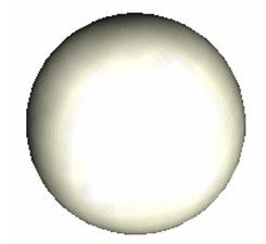
- Start with a solid or surface. If you have a solid, select it and use Create Surface From Solid to convert it into a surface. This example uses a sphere.
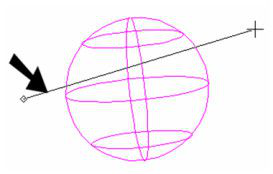
- Once you have a surface, activate 3D Slice in order to cut the surface . Make one or two slice lines.
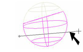
- Select and delete the sliced portions.
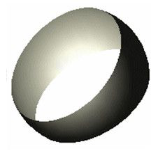
- Now select what's left of the surface and activate Create Solid From Surface. The surface is converted into a solid volume, within the boundaries of the original surface (holes are filled).
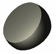
As a similar example, create a revolved surface . This is an ACIS object. Simply select it and make it a solid.
Create Surface from Face(s)
Default UI Menu: Modify/Modify 3D Objects/Create Surface/From Face(s)
Ribbon UI Menu:
Enables you to create a surface from selected planar facets of solid objects.
- Start with a solid that has planar facets. This example uses a 6-sided polygon extruded (using Simple Extrude) into a solid.
- Activate Facet Edit and select one or more faces.
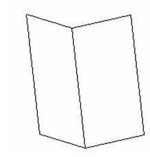
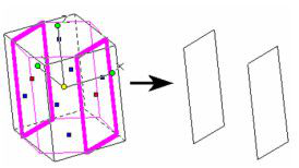
- Activate the Surface from Face(s) function, and the selected faces are now surfaces. The rest of the solid is deleted.
The selected faces do not have to be contiguous; surfaces can be created from any face(s).
- You will be prompted as to whether you wish to retain the original object.
Create Surface from Profile

Default UI Menu: Modify/Modify 3D Objects/Create Surface/From Profile
Ribbon UI Menu:
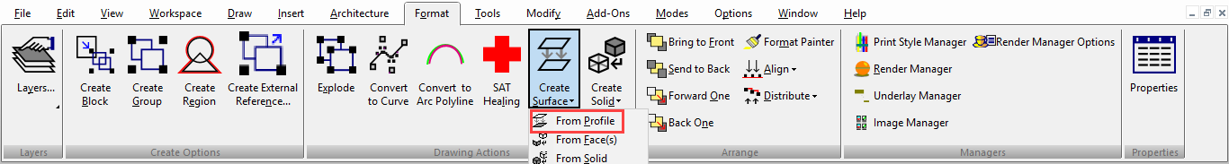
Enables you to create an ACIS surface within a closed profile. The profile can be 2D or 3D.
- Select one or more closed profiles.
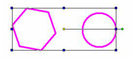
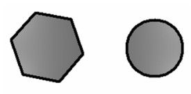
- Activate the Surface from Profile function, and the boundaries are filled by one or more surfaces. You can see the surfaces in render mode.
Create Surface from Solid
Default UI Menu: Modify/Modify 3D Objects/Create Surface/From Solid
Ribbon UI Menu:
Enables you to convert a solid volume into a hollow form; each solid face is converted into a surface.
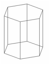
- Start by selecting one or more solids. This example uses a 6-sided polygon extruded (using Simple Extrude) into a solid.
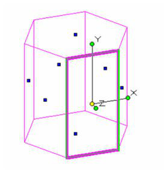
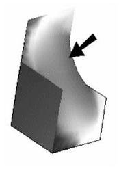
- Activate the Surface from Solid function, and the solid is hollowed out. Each of its facets is now a surface. To more easily see the results, activate Facet Edit and select one of the vertical faces.
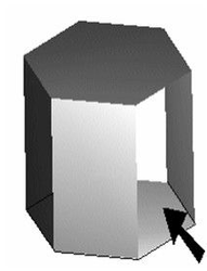
- Delete the face (using the Del key), and view the model in render mode to see the missing facet.
Note:If you used Facet Edit on a solid, without converting it into surfaces, this would be the result - the other faces would update to accommodate the deleted face.
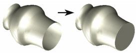
One usage of surfaces is to recreate a solid from the changed volume. If you delete a few more faces . . .
... you can then use Create Solid from Surface to add one missing face and produce a new solid.
Coordinate Systems
(Available in all TurboCAD Variants)
Default UI Menu: Modes/Coord System
Ribbon UI Menu:
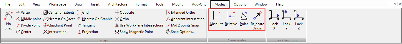
There are several types of coordinate systems you can use, and you can switch between them at any time. For example, when drawing the outer wall of a house, you may want to start the first wall at an absolute location. Each successive wall, however, will be defined by its length and angle relative to the first wall, so you would use polar coordinates for these points. To place walls at an X, Y distance from any other point, you could use relative coordinates. You can display the Coord System toolbar by right-clicking in any toolbar area and selecting Coord System. 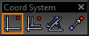
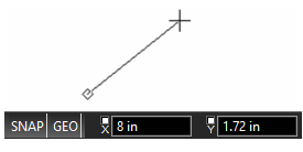
Coordinates, when entered manually, are entered in the Coordinate Fields, at the lower right corner of the screen. You can press Shift+Tab to jump to the first field in the Coordinate Fields, then press Tab to scroll through the remaining fields.
Tip: If you precede a coordinate with a $ sign, it will be interpreted as an absolute coordinate; if you precede it with an @ sign it will be interpreted as a relative coordinate; if you precede it with a > sign it will be interpreted as a polar coordinate.
Coordinate systems behave the same way in 2D and in 3D, but in 3D you need to be familiar with the concept of workplanes as well.
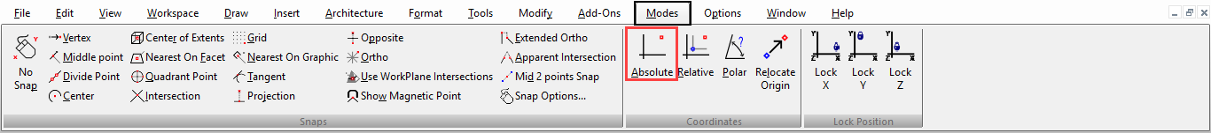
Absolute Coordinates
Default UI Menu: Modes/Coord System/Absolute Coords
Ribbon UI Menu:
Hotkey: A, Shift+ A

Cartesian (X, Y) coordinates relative to the fixed, absolute (WCS) origin.
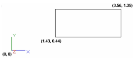
You can enter absolute X and Y values in the Coordinate Fields.
Locking Coordinates
By default, when you move the mouse around the screen, the values in the Coordinate Fields update dynamically. However, you can enter a value and lock it so that it will not change. Locking coordinates comes in handy when you need to only lock one field. For example, you can lock an X value and constrain all future points to be placed on the vertical line that passes through the X point.
Warning: Be sure to unlock coordinates when you are finished. As long as a coordinate is locked, you are not free to select the usual range of points.
To lock a value, check the lock box for the relevant field.  You can also use the Lock options in the Modes menu, or use the X, Y, or Z hotkeys.
Polar Coordinates
Hotkey: P, Shift+ P 
Default UI Menu: Modes/Coord System/Polar Coords
Ribbon UI Menu:
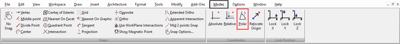
Polar (length and angle) coordinates relative to a specified origin. The relative origin (moving or fixed) behaves the same way as for Relative coordinates.
Tip: If you precede a coordinate with a > sign it will be interpreted as a polar coordinate.
You can enter the distance and angle to the selected point in the Coordinate Fields. 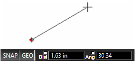
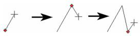
Relative Coordinates
Hotkey: R, Shift+ R 
Default UI Menu: Modes/Coord System/Relative Coords
Ribbon UI Menu:
Cartesian (X, Y) coordinates relative to a specified origin.
Tip: If you precede a coordinate with an @ sign it will be interpreted as a relative coordinate.
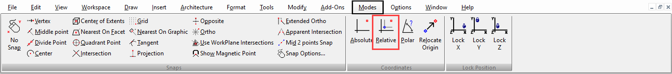
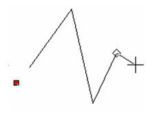
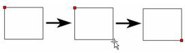
The relative origin can move as you work, relocating to each selected point, or it can remain fixed. The relative origin is controlled by the Fixed relative origin box on the Advanced Preferences page of the Program Setup. The relative origin is marked by a red square. You can use Relocate Origin (Shift+L) at any time to move it.
Relative Origin not fixed
Relative Origin fixed
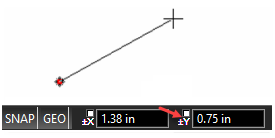
You can enter relative X and Y values in the Coordinate Fields. Note the +/- symbols, indicating that the distance is not absolute.
Relocate Origin
Hotkey:L, Shift+ L 
Default UI Menu: Modes/Coord System/Relocate Origin
Ribbon UI Menu:
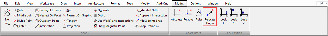
For Relative and Polar coordinates, moves the relative origin.
If you want to fix the relative origin in place, open the Advanced Preferences page and check Fixed relative origin.
WCS and UCS
The UCS (User Coordinate System) is the system in which you are working. By default, it is located to coincide with the WCS, but it can be moved. UCS axes can be displayed from Program Setup, and they appear wherever the origin is located.
The different coordinate systems in TurboCAD makes it easy to adjust to different drawing environments, for example if you draw round objects it may be easier to use polar coordinates.
| The World Coordinate System (WCS) is the internal, high accuracy (10 digits) and absolute coordinate system. To display the WCS axes, select View/Display/UCS Icon/ World Coordinate System, and they will appear at the lower left corner of the screen. The WCS indicator does not represent the origin; it indicates orientation. |  WCS Indicator WCS Indicator |
|---|---|
| The User Coordinate System (UCS) is the coordinate system in which you are working. By default, it is located to coincide with the WCS, but it can be moved and relocated by the user. UCS axes can be displayed by selecting View/Display/UCS Icon/ User Coordinate System, and they appear wherever the origin is located. Selecting an object using 2D Selector mode changes the UCS (and therefore the workplane) to the one attached to the selected object. |  UCS Indicator UCS Indicator |
In each coordinate system you also have an option to use either relative or absolute coordinates. The UCS indicator is helpful if you want to see how the UCS moves. You can display markers for the UCS and WCS via the Workspace menu, and customize the markers' appearance via the Preference page of the Program Setup (Options / Preference). The WCS indicator is always shown at the lower left corner of the screen; the UCS indicator is shown at the UCS origin. When using the 3D Selector, the selection shell local menu and Inspector Bar provide two options that relate selected objects to the UCS . Set UCS by Selector: Moves the UCS origin to the selection reference point.

Set Selector by UCS: Moves the selection to the UCS origin (similar to the Place on WorkPlane option for 2D objects).
Note: The 2D Selector always moves the UCS (Workplane) to the selection.