Openings
(Available in Platinum)
Default UI Menu: Architecture/Doors, Windows and Openings
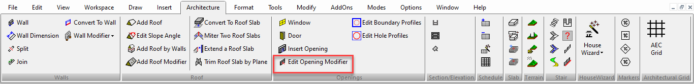
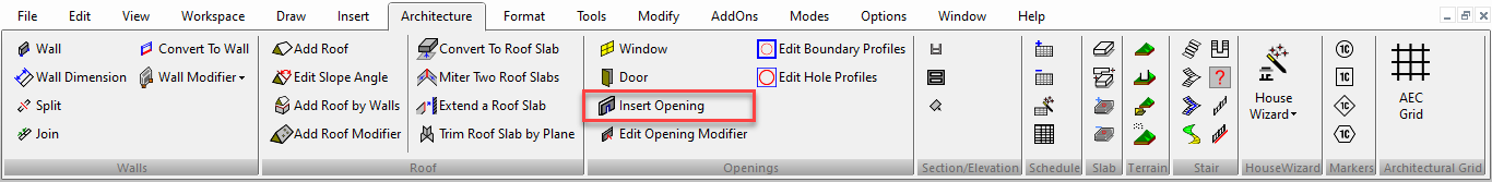
Ribbon UI Menu:

Enables you to insert a 2D / 3D opening into a wall, roof, or roof slab representing a window, door, etc.
Note: To insert actual "smart" windows and doors, see Windows and Doors
In this tool, each opening is represented by two blocks - a 2D and 3D view, so that the block can be seen in both orthographic and isometric views. The blocks must be created in advance before they can be inserted into a wall. The blocks do not have to be the same thickness as the walls, roofs, or roof slabs they will be inserted into.
Edit Opening Modifier

Default UI Menu: Architecture/Doors, Windows and Openings/Edit Opening Modifier
Ribbon UI Menu:
By default, when using the Insert Opening tool, an opening is inserted into a wall by creating a rectangular cutout, even when the block is not rectangular, as in the case of an arched doorway or a circular window.
For non-rectangular openings, you can apply a modifier that will define the shape of the cutout.
- In the Blocks Palette, select the 3D block whose cutout you want to modify, and click Edit Contents.
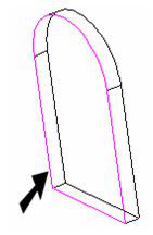
- Create the closed, 2D object you want to use as the cutout. Change the workplane if necessary. In this example, a polyline was added to the door face - an exact trace of the doorway shape.
- Activate Edit Opening Modifier. If a modifier was previously defined, it will be highlighted.
- Select the object to be used as the modifier.
- Select Finish from the local menu or Inspector Bar.
- In the Blocks Palette, click Finish Edit Content
- The openings now show the revised cutout shape.
Note: If you want to continue adding more openings, you will have to change the workplane back to Workplane by World.
Insert Opening
Default UI Menu: Architecture/Doors, Windows and Openings/Insert Opening
Ribbon UI Menu:
Options:
- Anchor to Wall / Anchor to Roof or Roof Slab - Specifys whether the open will snap to walls or roof objects.
- Elevation - Distance off of the workplane at which the opening will be set.
- Offset - Distance to the first adjacent wall. You can use this to exactly place the opening. however you can only specify one Offset: Offset or Offset 1
- Offset 1 - Distance to the second adjacent wall. You can use this to exactly place the opening.
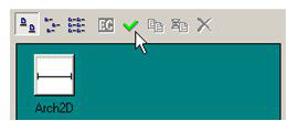
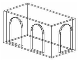
In this example, the opening has the following properties: For 2D representation: a block consisting of three lines
For 3D representation: a block consisting of an arched doorway, created by making a polyline (see Polyline) and extruding it (see Profile Objects and Face to Face Modifications ).
A value was assigned for Height, so that the block will be inserted above the floor. Remember, the blocks have to be created in advance, and are assigned to the opening in the Opening Properties.
- If necessary, change the workplane back to By World. You may have changed the workplane while creating one of the blocks, but the workplane must be along the bottom of the walls.
- Activate Insert Opening, and make sure Anchor to Wall is selected. (Anchor to Roof or Roof Slab is similar, except that openings will tilt themselves to fit along a sloped roof.)
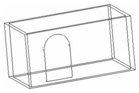
- Drag the opening to one of the walls. The block is dragged by its reference point, which can be changed if needed.
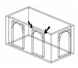
- The block aligns itself to the wall, and cuts the opening.
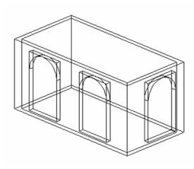
- Drag more blocks onto the walls. The block will change its alignment to fit any wall.
Note: This tool only creates rectangular cutouts, even if the block is non-rectangular. You can change this by modifying the block. See Edit Opening Modifier
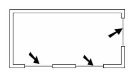
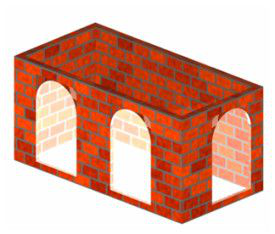
In Plan view, the openings are represented by the 2D block.
If you assign the 3D block a material such as glass (in the 3D page of its Properties), and assign a brick material for the walls, you can see the results in render mode.
Opening Properties
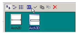
Before an opening can be inserted, you must select the 2D and 3D blocks (previously created) that will be used to represent it. This is done in the Properties window - opened by right-clicking on the Insert Opening icon.
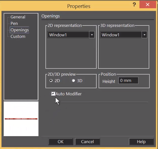
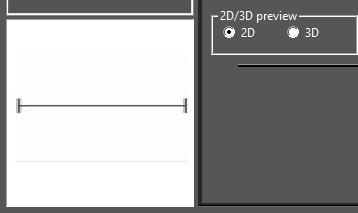
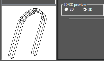
2D/3D representation: The blocks that will be used to represent the opening. The 2D block will be used in plan views; the 3D block will be used in all other views. 2D/3D preview: The preview is displayed on the left side of the window, so that you can verify the selected block is correct. Position / Height: The distance from the workplane where the opening will be inserted. This is useful for windows that need to be located a certain height from the floor.
Auto Modifier: Inserting an opening with a non-rectangular outline, if checked.
The Auto Modifier option to the Openings Properties allows the Opening to be inserted with a non-rectangular outline.
Tip: If you want to create and save more than one type of opening, create separate styles (accessed from the General page of the Properties window). This way you will not have to recreate properties of openings you have already inserted. See Property Value Presets