Stairs
(Available only in Platinum)
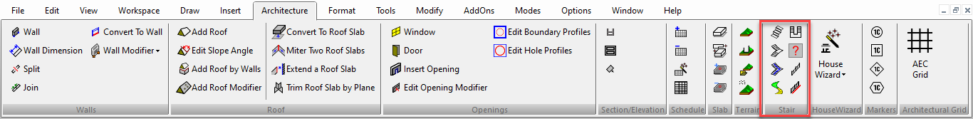
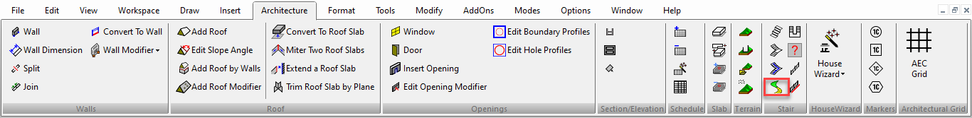
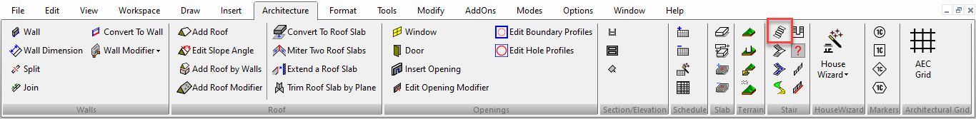
Default UI Menu: Architecture/Stairs and Railings
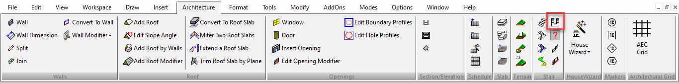
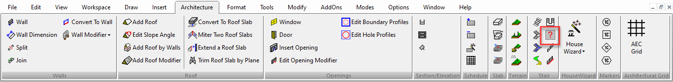
Ribbon UI Menu:
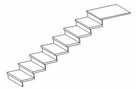
These tools enable you to create four types of staircases: straight, spiral, multi-landing, and U-shaped.
Editing Stairs
The Edit Tool can be used to move or resize walls.
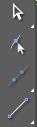
- This example shows a stair. Activate the Edit Tool and click the stair you want to change.
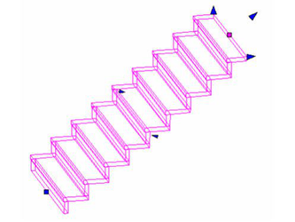
- If you click and drag a node, you can move it anywhere.
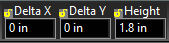
- The Inspector bar gives you the option to apply a specific delta x and y for any selected node. It also gives the ability to edit the Height of the stairs.
Multi Landing Stair
Default UI Menu: Architecture/Multi Landing Stair
Ribbon UI Menu:
Creates two or more lines of stairs.
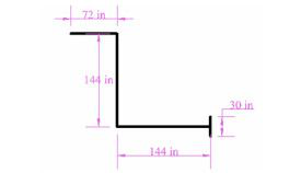
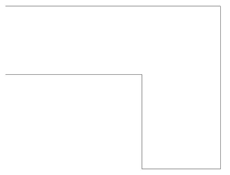
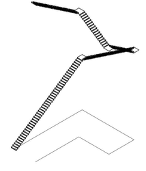
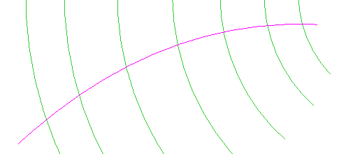
- For reference, it may be helpful to lay out the stairs using lines in World Plan. In this example, the right-most vertical line represents the width of the stairs, and the other lines represent the path of the stair case.
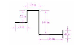
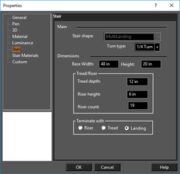
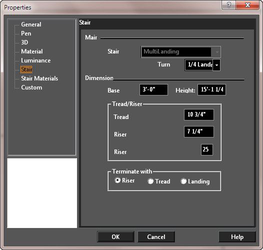
- Activate Multi Landing Stair and open the Properties to the Stair page. This example shows 1/2 Landing. The remaining parameters control the vertical and horizontal dimensions of each stair.

Note: Other stair properties, such as tread and riser thickness, nosing length, and materials can be set using the Style Manager. See Stairs Styles. Once you have styles defined, you can set a stair's style in the General page of the Properties.
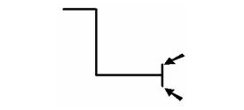
- The first two clicks define the width of the stairs, or you can use the Inspector Bar. (If this value is different than the Base Width set in the Properties, then Base Width will be overridden. However, you can always change this value later in the Properties.)
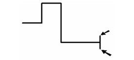
- The next clicks, or values in the Inspector Bar, define the path of the stairs. This example uses five segments.
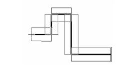
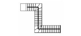
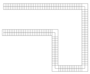
- Select Finish to create the stairs. In World Plan, you can see whether the number of stairs is correct. In this example, there is one stair too many.
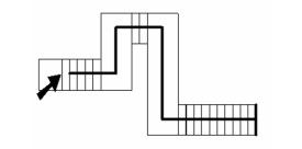
- To correct this, open the stair's Properties and set the correct Riser count.
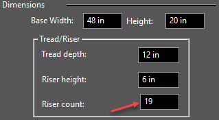
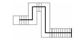
Now the number is correct.
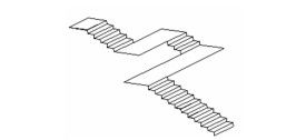
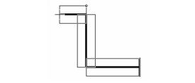
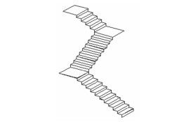
- In Isometric view, this is the 1/2 Landing staircase. The second, fourth, sixth, etc. segments of the stair path are created as landings.
- For the other turn types, each segment is created as a staircase. So start with a stair line like this, with fewer segments.
- Select 1/4 Turn, and set the Riser Count to an approximately accurate value (it can always be corrected later).
- As before, set the width of the stairs.
- Then select the stair path.
- Select Finish, and adjust the Riser Count if necessary.
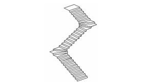
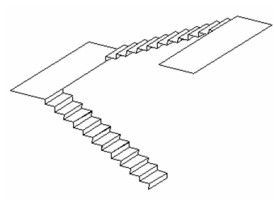
This is the 1/4 Turn staircase in Isometric view. There are no landings; the stairs proceed along the turns.
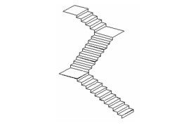
This would be the result if you selected 1/4 Landing. Each segment is a staircase, and square landings are created between each segment.
MultiLanding Stair by Path
Default UI Menu: Architecture/Multi Landing Stair by Path
Ribbon UI Menu:
Creates stair basded on a pre-existing 2D Polyline compose of line segments. Don't use arc segments. 3D polylines may be used but only their x, y coordinate geometry will be used in the creation of the stair.
- In World Plan draw a plyline that will bes used to create the stair.
- Activate MultiLanding Stair by Path and open the Properties to the Stair page. This example shows 1/4 Landing. The remaining parameters control the vertical and horizontal dimensions of each stair. Close Properties. For most multilanding stairs 1/4 landing is the best option.
Note: Other stair properties, such as tread and riser thickness, nosing length, and materials can be set using the Style Manager. See Stairs Styles. Once you have styles defined, you can set a stair's style in the General page of the Properties.
- Click on the polyline.
- A preview of the stair will appear.
- Right click and select Fiinish to complete the stair.
Stair with reference polyline. Modified to 1/2 Landing. 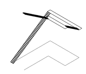
Spiral Stair
Default UI Menu: Architecture/Spiral Stair
Ribbon UI Menu:
Creates a spiral staircase.
- Activate Spiral Stair and open the Properties to the Stair page. This example will be Clockwise. The remaining parameters control the vertical and horizontal dimensions of each stair.
Note: Other stair properties, such as tread and riser thickness, nosing length, and materials can be set using the Style Manager. See Stairs Styles. Once you have styles defined, you can set a stair's style in the General page of the Properties.
- The next three clicks define the plan dimensions of the stairs. The first sets the center, the second sets the interior radius, and the third sets the exterior radius. These values can also be set in the Inspector Bar.
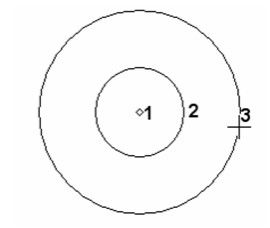
The space between the interior and exterior radius is the width of the stairs. If this value is different than the Base Width set in the Properties, then Base Width will be overridden. However, you can always change this value later in the Properties.
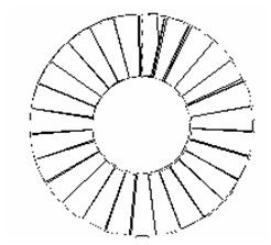
- Next, set the angle from the circle center, where the first stair will be.
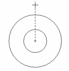
The spiral staircase is created.
This is the clockwise spiral staircase in Isometric view. The height of the staircase is the Riser Count times Riser Height, both of which can be adjusted in the Properties. 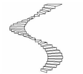
Stair Properties
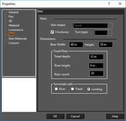
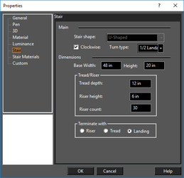
The Stair page of the Properties contains parameters for defining the size of treads and risers.

Stair shape and Turn type: These vary depending on the type of stair you are creating. These options are explained for each stair type.
Base Width: The width of the stairs. You can define this here, or when defining the stair geometry.
Height: The height of the stairs. You can define this here or when selecting stair by edit tool.
Tread depth: The horizontal depth of each step.
Riser height: The vertical height of each step.
Riser count: The number of stairs. You can define this here, or when defining the stair geometry.
Terminate with: Defines what will appear at the top of the stairs.
Note: Other stair properties, such as tread and riser thickness, nosing length, and materials can be set using the Style Manager. See Stairs Styles. Once you have styles defined, you can set a stair's style in the General page of the Properties.
Straight Stair

Default UI Menu: Architecture/Sraight Stair
Ribbon UI Menu:
Inserts a straight line of stairs.
The first two clicks define the stair width, and the third defines the length. After the stairs are created, you can use the Properties to change the width, number of risers, etc.
U-Shaped Stair
Default UI Menu: Architecture/U-Shaped Stair
Ribbon UI Menu:
Creates a line of stairs that doubles back on itself.
- Activate U-Shaped Stair and open the Properties to the Stair page. This example will be Clockwise with a 1/2 Landing. The remaining parameters control the vertical and horizontal dimensions of each stair.
Note: Other stair properties, such as tread and riser thickness, nosing length, and materials can be set using the Style Manager. See Stairs Styles. Once you have styles defined, you can set a stair's style in the General page of the Properties.
- The next three clicks define the plan dimensions of the stairs. The first two clicks sets the stair width and angle. The third click sets the offset - this is the distance between the exterior edge of one stair run and the interior edge of the other stair run. These values can also be set in the Inspector Bar.
The space between the first two clicks is the width of the stairs. If this value is different than the Base Width set in the Properties, then Base Width will be overridden. However, you can always change this value later in the Properties. The U-shaped staircase is created.
This is the clockwise staircase in Isometric view. The height of the staircase is the Riser Count times Riser Height, both of which can be adjusted in the Properties. Each stair run has half the Riser Count, and a landing runs between them.
This would be the result if you selected 1/2 Turn. Each segment is a staircase, and there are no landings. The total number of risers is divided among the three sets of stairs.
Stair by Linework
Default UI Menu: Architecture/Stair by Linework
Ribbon UI Menu:
This tool create stairs from a set of lines / polylines / arcs / curves. To create the stairs:
- Select the tool
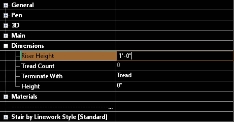
- Open the Selection Info palette, and set the Riser height.
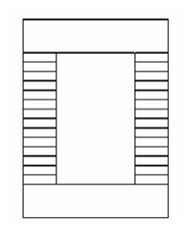
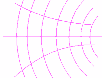
Using this pattern as an example:
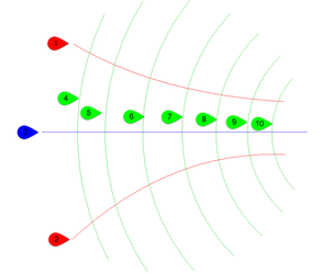
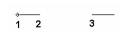
- Select 2D polyline/circular arc for the Stair's Linework Left side path (1)
Note: the selection of the right/left side define the direction of the stairs.
- Select 2D polyline/circular arc for the Stair's Linework right side path (2)
- Select 2D polyline/circular arc for the Stair's Linework path (3)
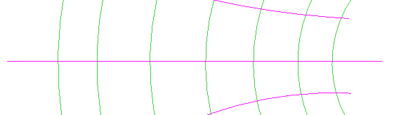
- Select 2D polyline/circular arc for the Stair's Linework Tread's Riser path (4-10)
Note: It is important to select the riser in sequence from first to last in order to get predictable results.
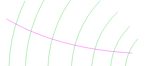
- After you have chosen two risers you will be prompted to Select 2D polyline/circular arc for the Stair's Linework Tread's Riser path or use "Finish" from local menu to create stair. Select additional risers or click Finish in the local menu or Inspector bar to complete the stair.
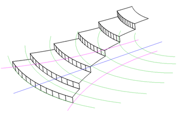
Note: at anytime in steps 3-6 you can opt to use One Step Back from the local menus or Inspector bar.