Patterns
(Available only in Platinum)
Default UI Menu: Draw/3D Object/3D Pattern
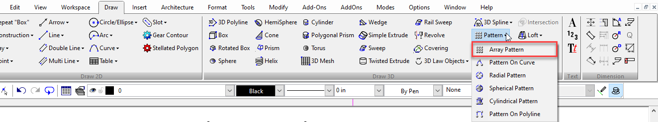
Ribbon UI Menu:
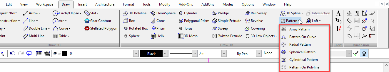
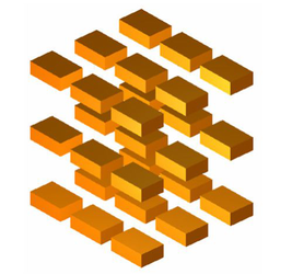
Patterns are arrays of objects copied in specific arrangements, and controlled parametrically. Patterns of solid objects act as solid and they and/or their elements can be manipulated by 3D tools, like Bend, and patterns can be Booleaned with other 3D objects. There are six pattern tools: Array, On curve, Radial, Spherical, Cylindrical, Pattern on Polyline.
Associative Arrays
You can use the pattern tools to create 2D and 3D arrays of 2D objects, 3D objects and blocks. Update the arrays in arrangement, number, columns, levels, and rows.
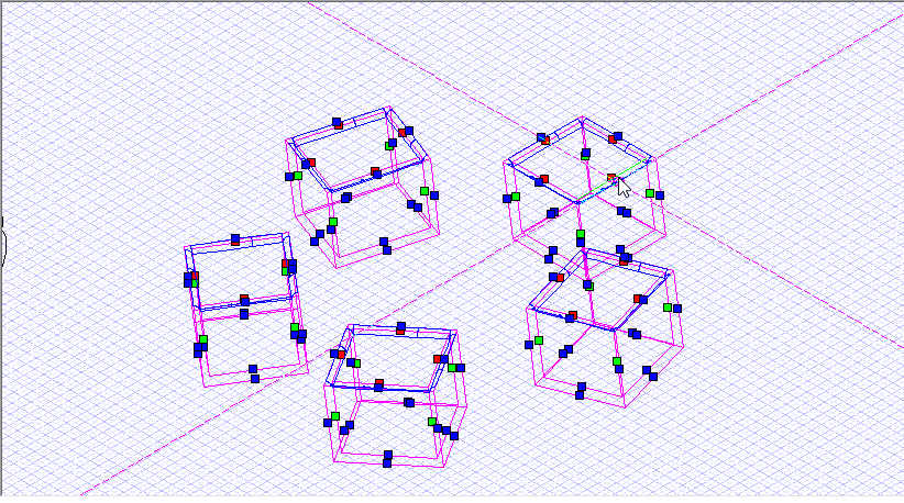
Applying Solid Operations to the Patterns Simultaneously:
Apply to Pattern: This local menu option Apply to Pattern allows users to simultaneously apply solid operation for all Pattern elements This option is available for the following operations which can be applied on the pattern objects simultaneously: Fillet Edges, Chamfer Edges, Face offset, Shell Solid.
Example:
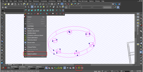
Here's an example using Fillet Edges using Apply to Pattern.
- Activate Fillet Edges
- Select an object in the Pattern
- Select "Apply to Pattern" from the local menu/Inspector Bar

-
The Fillet Object previews for all the pattern elements simultaneously.
-
-
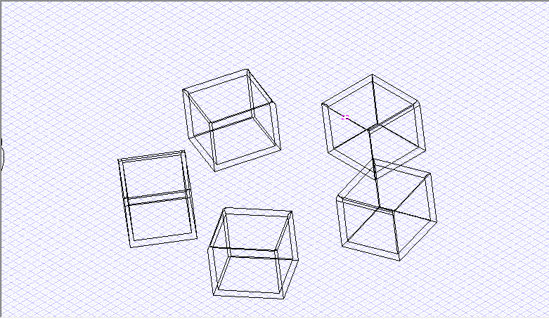
Click Finish from the local menu and changes get applied to all pattern elements.
-
Array Pattern
Default UI Menu: Draw/3D Object/3D Pattern/Array Pattern
Ribbon UI Menu:
Creates a rectilinear array composed of columns, rows and levels.
- Select the Array Pattern tool.
- In the Inspector bar set the Number of columns, rows and levels.
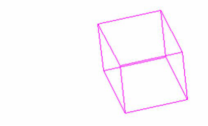
- Select a 3D solid.
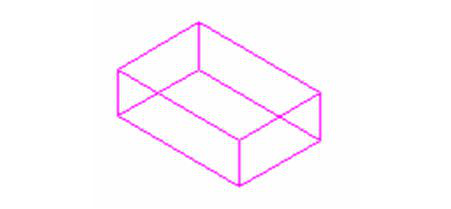
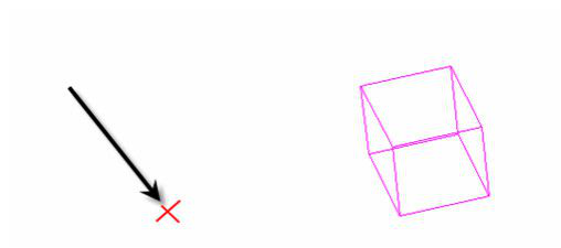
- Click to specify the origin of the array.
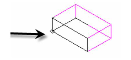
- Move the cursor and click to set the X axis of the array.
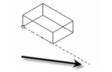
- Move the cursor and click to set the Y axis of the array.
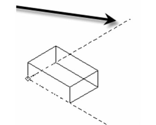
- Move the cursor and click to set the Z axis of the array.
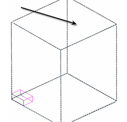
- The array is created.
The axis values set the distance from center to center of the source object.
Warning: You must have at least two rows to have more than one levels in this array. Reducing rows to one will eliminate the level option until more rows are added.
Local menu options: Create Association: Creates an association between the pattern and the destination object. If subsequently the destination object is edited the pattern will update to reflect the changes made. The Leave Destination and By Entity options must be active for associations to be available. Leave Source: If this option is on the original 3D object (source) will remain. If it is off the object will be deleted. Leave Destination: If this option is on the 3D object used as for By Entity will remain. If it is off the object will be deleted. By Entity: If this option is on you can select an existing box to set the axis size of the array. With this option on you select the box instead of specifying the origin and axis values. The axis values will be the axis values of the box. Fit Pattern: If this option is on the axis lengths will define the total length between the centers of the outermost elements in the array along each axis. In other words "fit" within the lengths. If the option is off the axis lengths specify the distance between centers of adjacent objects. Rectangular Base: Forces the the Y-axis to be 90 degrees to the X-axis Hexagonal: Creates a hexagonal grid array. If this option is on you will only be allowed to enter an X-axis, unless you use the By Entity setting. Checker Board: Creates an alternating checker board array. 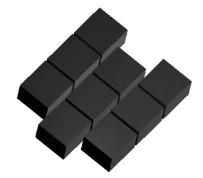
Note: Array Properties are available only through the Selection Info Palette..
Array Properties: The properties available will vary depending upon how you created your pattern. Fit: If on he array will be fit within the specified axes lengths. Otherwise the axis lengths specify the distance between the centers of objects. Cols: Sets the number of columns Rows: Sets the number of rows Levels: Sets the number of levels. X-axis Length: Sets the X axis length. Y-Axis Length: Sets the Y axis length. Height: Sets the Z axis length.
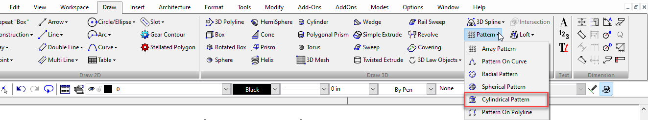
Cylindrical Pattern
Default UI Menu: Draw/3D Object/3D Pattern/Cylindrical Pattern
Ribbon UI Menu:
- Select the Cylindrical Pattern tool.
- Select a 3D solid.
- Click to set the center of radial pattern.
- Click to set the radius of the pattern.
- Click to set the height of the pattern.
Local menu options: Leave Source: If this option is on the original 3D object (source) will remain. If it is off the object will be deleted. Create Association: Creates an association between the pattern and the destination object. If subsequently the destination object is edited the pattern will update to reflect the changes made. The Leave Destination and By Entity options must be active for associations to be available By Entity: If this option is on you can select an existing circle or an arc or a circular curve on a 3D object to set the size of the array. With this option on you select the circle instead of specifying the center and radius values. Fit Pattern: If this option is on the height will define the total distance between the top and bottom of the array. In other words "fit" within the height. If the option is off the height specifies the distance between each of the axial sets. Hexagonal: Creates a hexagonal alternating cylindrical array.
Radius: Sets the radius for the pattern.
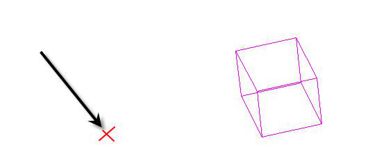
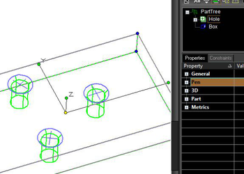
Hole Patterns
You can use the pattern tool to layout holes.
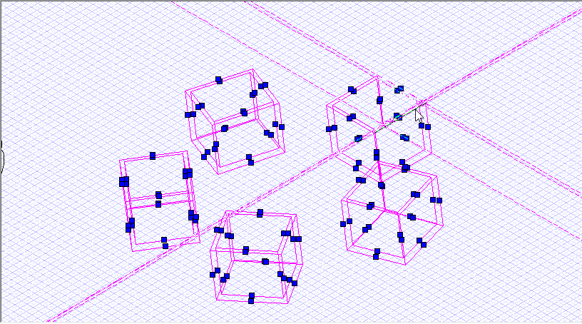
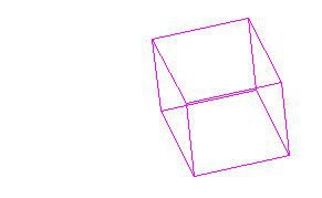
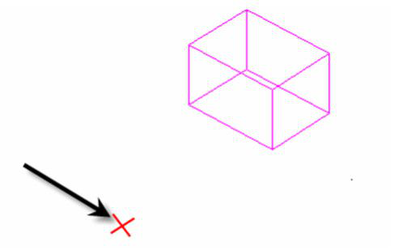
- Create a cube and a point.
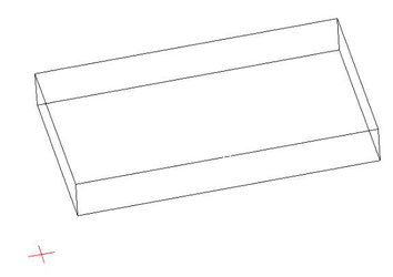
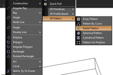
- Start the Radial Pattern tool
-
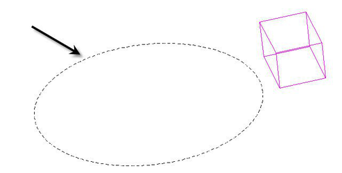
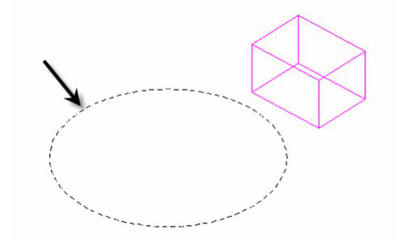
Click the Point as the source object, define the pattern path on the top face of cube. A pattern of points will be created.
-
Start the Hole Tool.
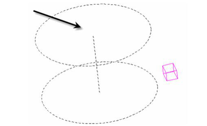
- Select the plane face, select the pattern of points, a PartTree with hole operation will be created.
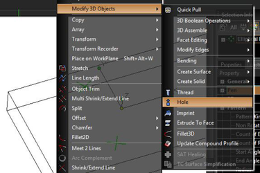
- Select the pattern object in the drawing, and change count of elements, for example. The count of holes in Part Tree will be changed accordingly to copies of elements of Pattern Of Points.
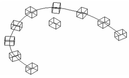
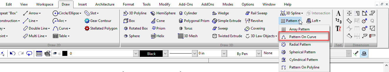
Pattern by Curve
Default UI Menu: Draw/3D Object/3D Pattern/Pattern On Curve
Ribbon UI Menu:
Creates an array of objects along an existing curve. Beziers can be used as the curve, so can 2D or 3D splines. Polylines, circles, arcs and lines cannot be used.
- Select the Pattern by Curve tool.
- In the Inspector bar specify the number of Sets, then press Enter.
- Select a 3D solid.
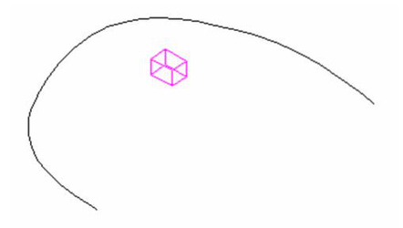
- Click on a curve to finish the pattern.
Local menu options: Create Association: Creates an association between the pattern and the destination object. If subsequently the destination object is edited the pattern will update to reflect the changes made. The Leave Destination option must be active for association to be available. Leave Source: If this option is on the original 3D object (source) will remain. If it is off the object will be deleted. Leave Destination: If this option is on the curve will remain. If it is off the curve will be deleted. Non Rotate: If this option is selected the tool creates the designated pattern but the arrayed objects retain the orientation of the source object and are not rotated at each position.
Array Properties: The properties available will vary depending upon how you created your pattern. Fit: If on he array will be fit within the specified axes lengths. Otherwise the axis lengths specify the distance between the centers of objects. Count of Elements: Sets the number of items in the pattern. Non Rotate: If this option is selected the tool creates the designated pattern but the arrayed objects retain the orientation of the source object and are not rotated at each position.
Pattern by Polyline
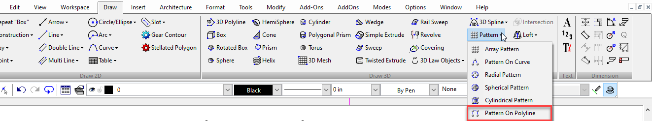
Default UI Menu: Draw/3D Object/3D Pattern/Pattern On Polyline
Ribbon UI Menu:
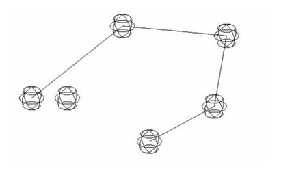
 Creates an array of objects along and 2D or 3D polyline.
- Select the Pattern by Polyline tool.
- In the Inspector bar specify the number of Sets, then press Enter.
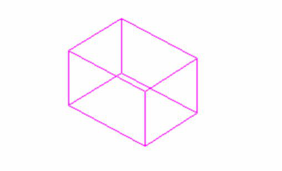
- Select a 3D solid.
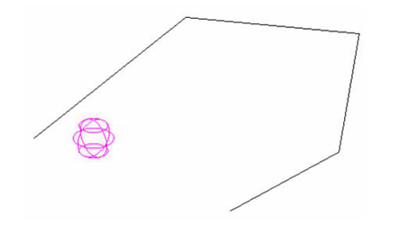
- Click on a polyline to finish the pattern.
Local menu options: Create Association: Creates an association between the pattern and the destination object. If subsequently the destination object is edited the pattern will update to reflect the changes made. The Leave Destination option must be active for association to be available. Leave Source: If this option is on the original 3D object (source) will remain. If it is off the object will be deleted. Leave Destination: If this option is on the curve will remain. If it is off the curve will be deleted. Non Rotate: If this option is selected the tool creates the designated pattern but the arrayed objects retain the orientation of the source object and are not rotated at each position.
Array Properties: The properties available will vary depending upon how you created your pattern. Fit: If on he array will be fit within the specified axes lengths. Otherwise the axis lengths specify the distance between the centers of objects. Count of Elements: Sets the number of items in the pattern. Non Rotate: If this option is selected the tool creates the designated pattern but the arrayed objects retain the orientation of the source object and are not rotated at each position.
Radial Pattern
Default UI Menu: Draw/3D Object/3D Pattern/Radial Pattern
Ribbon UI Menu:
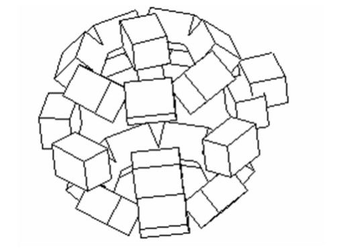
Creates a variety of radial array patterns.
- Select the Radial Pattern tool.
- Select a 3D solid.
- Click to set the center of radial pattern.
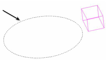
- Click to set the radius of the pattern.
Local menu options:
Create Association: Creates an association between the pattern and the destination object. If subsequently the destination object is edited the pattern will update to reflect the changes made. The Leave Destination and By Entity options must be active for associations to be available. Leave Source: If this option is on the original 3D object (source) will remain. If it is off the object will be deleted. Leave Destination: If this option is on the 3D object used as for By Entity will remain. If it is off the object will be deleted. By Entity: If this option is on you can select an existing circle or an arc or a circular curve on a 3D object to set the size of the array. With this option on you select the circle instead of specifying the center and radius values. Elliptical Pattern: If this option is selected the tool creates a circular pattern. The number of rings is ignored. This is the default option. Polar Grid Pattern: If this option is selected the tool creates a polar grid pattern, similar to the polar longitude lines on a globe. The angular number is ignored. Radial Pattern: If this option is selected the tool creates a radial pattern, similar to the spokes of a wheel. Non-Rotate: If this option is selected the tool creates the designated pattern but the arrayed objects retain the orientation of the source object and are not rotated at each position. This option is not available for if Polar Grid is selected. Fit Pattern: If this option is on the radius will define the total distance between the center of the outermost elements in the array and the center of the array. In other words "fit" within the radius. If the option is off the radius specifies the distance between centers of adjacent rings. This option is not available for elliptical patterns. Hex Symmetry: If this option is on the resulting Polar grid pattern will use a hexagonal arrangement for the spokes instead of a quadrant arrangement. This option is only available if Polar grid is selected.. On Arc: If this option is selected the tool will prompt you to specify the desired arc after you specify the radius. The arc is specified by selecting two points in sequence. This option will be ignored if By Entity is selected.
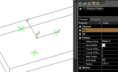
Array Properties
The properties available will vary depending upon how you created your pattern. Fit: If this option is on the array will be fit within the specified axes lengths. Otherwise the axis lengths specify the distance between the centers of objects. Count of Elements: Sets the number of items in the pattern. Start Angle: Sets the angle at which the pattern starts. End Angle: Sets the angel at which the pattern ends. Non-Rotate: If this option is selected the tool creates the designated pattern but the arrayed objects retain the orientation of the source object and are not rotated at each position. This option is not available for Polar Grid is selected. Fit Pattern: If this option is on the radius will define the total distance between the center of the outermost elements in the array and the center of the array. In other words "fit" within the radius. If the option is off the radius specifies the distance between centers of adjacent rings. This option is not available for elliptical patterns. Hex Symmetry: If this option is on the resulting Polar grid pattern will use a hexagonal arrangement for the spokes instead of a quadrant arrangement. This option is only available if Polar grid is selected.. Radius: Sets the radius for the pattern.
Array Properties
The properties available will vary depending upon how you created your pattern. Count of Latitudes: Sets the number of latitudes in the pattern. Radius: Sets the radius for the pattern.
Elliptical Patterns have the following options:
Count of Rings: set the number of concentric rings. Radius Step: specifies the distance between each concentric ring. Z-offset: sets the height offset for concentric rings. Only available if the value of Count of Rings > 0.
Snaps and Dimensions in 3D
Snaps work in 3D, but are most are projected onto the current workplane. Therefore, to apply a dimension to a 3D object, you must set the workplane to the plane where you want the dimension to appear. In other words, you can display projected measurements in 3D. For ACIS solid objects, you can apply Radius and Diameter dimensions to arc-based objects. You must turn on Degenerative Faceting in the ACIS page (Options/ACIS). These dimensions are non-associative.
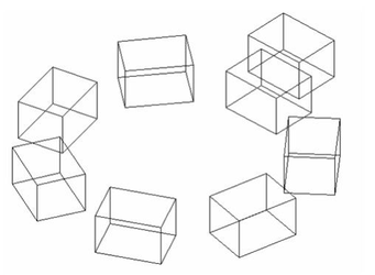
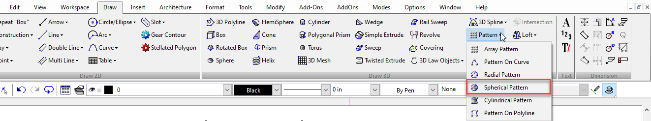
Spherical Pattern
Default UI Menu: Draw/3D Object/3D Pattern/Spherical Pattern
Ribbon UI Menu:
- Select the Spherical Pattern tool.
- In the Inspector bar set the Number of latitudes.
- Select a 3D solid.
- Click to set the center of radial pattern.
- Click to set the radius of the pattern.
Create Association: Creates an association between the pattern and the destination object. If subsequently the destination object is edited the pattern will update to reflect the changes made. The Leave Destination and By Entity options must be active for associations to be available. Leave Source: If this option is on the original 3D object (source) will remain. If it is off the object will be deleted. Leave Destination: If this option is on the 3D object used as for By Entity will remain. If it is off the object will be deleted.
Use Patterns as Compound Profiles
You can use patterns of 2D objects as a compound profile.
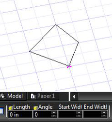
- Draw a Polyline
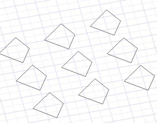
- Create an Array pattern of Polylines.
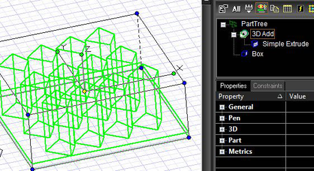
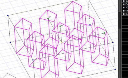
- Start the Simple Extrude tool, Select the Use Compound Profile option. Select the pattern of polylines as the profile for the Simple Extrude operation. The result is Simple Extrude object.
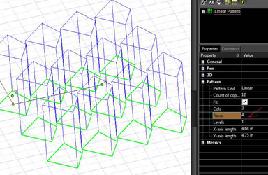
- Select the Pattern in the drawing and change Rows value, for example. Simple Extrude will be changed accordingly to pattern properties.
- A Simple Extrude can be added to something using Boolean Add. Short Part Tree for such a complex object.