Section
Default UI Menu: Modify/Section
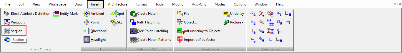
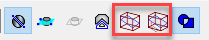
Ribbon UI Menu:
Creates a 2D or 3D section of one or more 3D solid or surface objects.
The resulting sections are grouped into one object.
The sections are considered a "Group of graphics," which can be viewed and manipulated in the Selection Info Palette
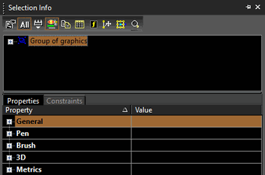
For a 2D section, the "Group of graphics" is composed of lines, circles, ellipses, circular arcs, elliptical arcs and/or splines as needed to create the section. For a 3D section (Section by Closed Polyline), the "Group of graphics" is composed of solids and/or surfaces generated by the intersection of the selected objects and the normal extrusion of the closed polyline.
Note: The 3D Slice tool is similar, but uses the specified plane to divide the object into new objects.
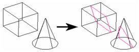
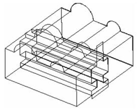
Section by Closed Polyline
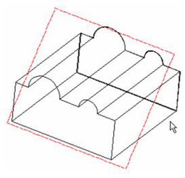
Creates a 3D section by using a closed polyline, rectangle, or polygon to cut through the solid. The section is normal to the plane of the polyline.
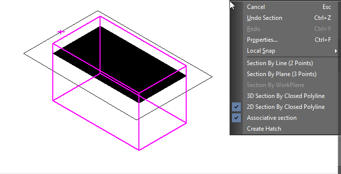
- Select 2D or 3D Section by Closed Polyline from the local menu or Inspector Bar.
- Select the object to section. You can use Shift to select more than one object, or use a selection window (first click outside the objects, then drag the window).
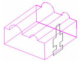
- Select the closed polyline.
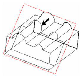
- The 2D/3D section is created.
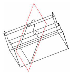
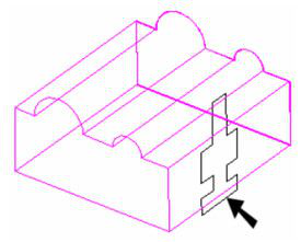
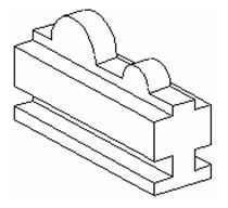
You can view the 3D section more clearly by removing the original solid. (The render mode here is Hidden Line.)
If the local menu option “Associative Section” is enabled, then the section created will be associated with the section polyline and the 3D object. This is, with the changes made in the associated Polyline or the 3D object, the section created will also be updated.
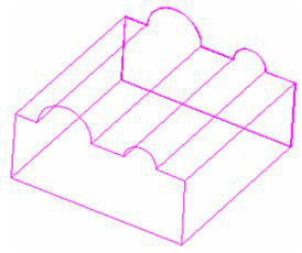
Section by Line
Creates a section perpendicular to the current view, by defining two points. This is the default option.For details on workplanes, see Workplanes
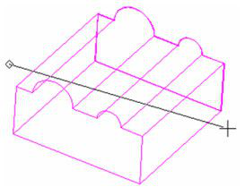
- Select Section by Line (2 Points) from the local menu or Inspector Bar.
- Select the object to section. You can use Shift to select more than one object, or use a selection window (first click outside the objects, then drag the window).
- Select two points. The section plane will pass through the line defined by these points, in the direction normal to the current view (into the screen).
- The section is created, but in the current view it appears as a line.
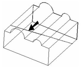
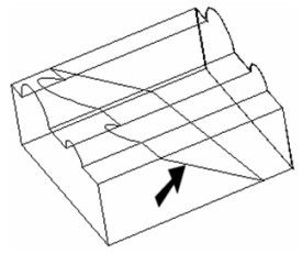
You can rotate the view to see the section.
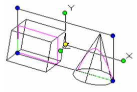
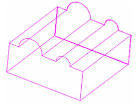
Section by Plane
Creates a section by defining the sectioning plane. The plane is defined by three points.
- Select Section by Plane (3 Points) from the local menu or Inspector Bar.
- Select the object to section. You can use Shift to select more than one object, or use a selection window (first click outside the objects, then drag the window).
- Select three points to define the sectioning plane.
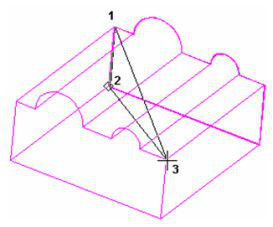
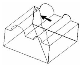
- The section is created.
Section by Workplane
Creates a section by using the current workplane as the sectioning plane.
- Select Section by Workplane from the local menu or Inspector Bar.

- Select the object to section. You can use Shift to select more than one object, or use a selection window (first click outside the objects, then drag the window).
Note: To section multiple objects, start out using a different option - Section by Line or Section by Plane. Use Shift to select the objects to slice, then click the Section by Workplane icon.
The section is created.
You can rotate the view to see that the section lies on the workplane.