Curves
(Available in all TurboCAD Variants)
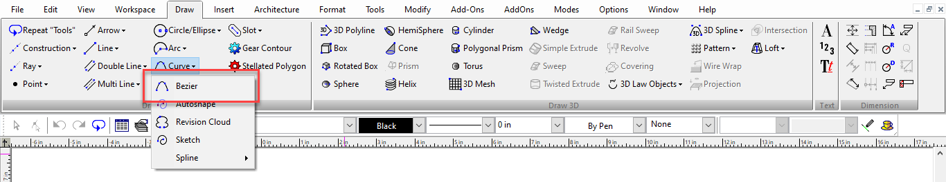
Default UI Menu: Draw/Curve
Ribbon UI Menu:
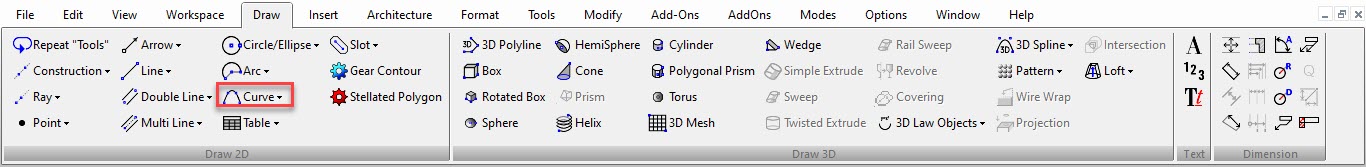
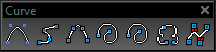
Tools for drawing splines, Bezier curves, sketches, and revision clouds. You can display the Curve toolbar by right-clicking in any toolbar area and selecting Curve.
Autoshape
Default UI Menu: Draw/Curve/Autoshape
Ribbon UI Menu:
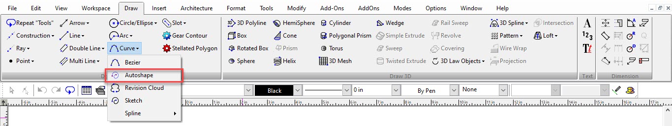
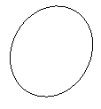
The Autoshape tool allows you to quickly create standard shapes just by sketching. The sketched shape will automatically recompose into a standard object depending on the shape of the sketch. The objects include: Lines, Polylines, Rectangles, Polygons, Triangles Arcs, Circles, Ellipses, Ellipse / Circles If the sketch closely approximates a elliptical path an ellipse will be generated. 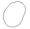

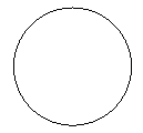
 If the radii of the computed ellipse are almost equal, then a circle is drawn.
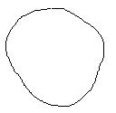
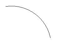
 If the sketch closely approximates a circular path but is open an arc will be generated.
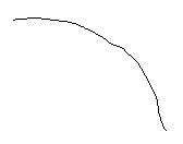

Line A single quick dash will result in a line. 

 Polyline If the end points are closely located the resulting polyline will be closed. If the angle between the nearest computed line segments is close to to 90 degrees, right angle is created.
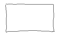
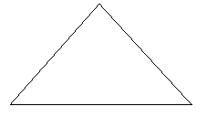
 A closed polyline with 3 points becomes a triangular Polygon.
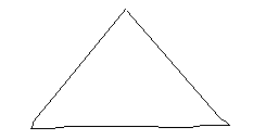
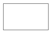
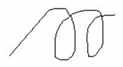
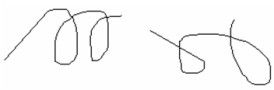
 A closed polyline with 4 points becomes a rectangular Polygon. Bezier Curve If the sketch does not approximate a regular shape a Bezier curve will be created. The curve can be closed or open.
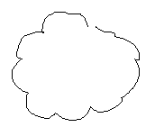
Curve Properties
Curve properties can be set on the Curves page of the Properties window. 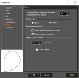 Number of segments between adjacent control points: Curves are composed of many small line segments drawn between control points. A high number of segments will yield a smoother curve; a low number will make the curve appear more jointed.
High number of segments 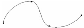 Low number of segments
 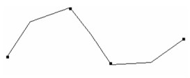 Bezier Curve
 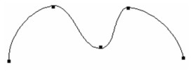 Spline Curve
 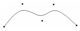 Bezier Curve
Options: If the curve is a Bezier curve, the following options are available: Show additional control points: Additional control points will be displayed when Edit Node mode is active (see Edit Tool and Editing Splines and Bezier Curves ). This also enables the Keep the Curve Smooth option.
Regular control points in Edit Node mode 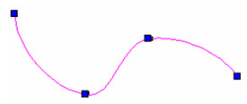
Additional control points in Edit Node mode 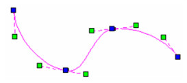 Keep the curve smooth: If checked, the additional control points at each node remain linear, so that no sharp corners can be created at a node. If not checked, you can move each additional node independently.
Keep Curves Smooth - additional nodes remain linear 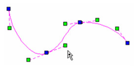
Keep Curves Smooth disabled 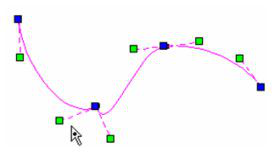
Warning: Modifying tools such as Split or Trim may alter a curve drastically, because the curve loses the influence of deleted control points.
Spline Curve Options: The degree value creates a spline of n-th order, which affects the spline smoothness. Show Frame: If checked, a polyline frame will be displayed connecting the curve's control points. This provides visual feedback about how the curve is drawn.
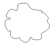
Revision Cloud

Default UI Menu: Draw/Curve/Revision Cloud
Ribbon UI Menu:
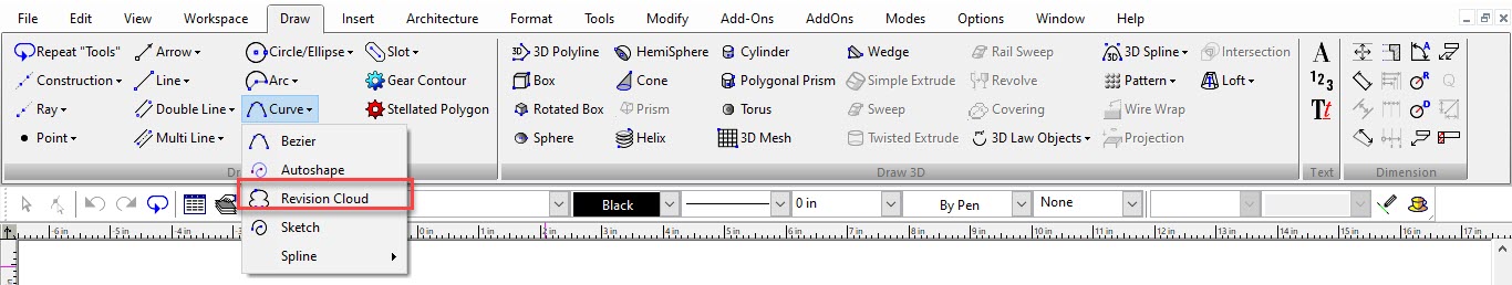
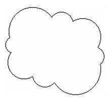
Creates uniform revision clouds. These are most commonly used in Paper Space, but the tool is available in Model Space as well.
- Before selecting the start point, select Number of segments from the local menu. The default number is 1, and each segment consists of two arcs.
- Select the start and endpoints of the first segment.
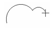
- Continue selecting points for more segments.
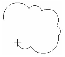
- When finished, select Finish (Alt+F) from the local menu, or select Close (Alt+C) to join the endpoints.
Sketch

Default UI Menu: Draw/Curve/Sketch
Ribbon UI Menu:
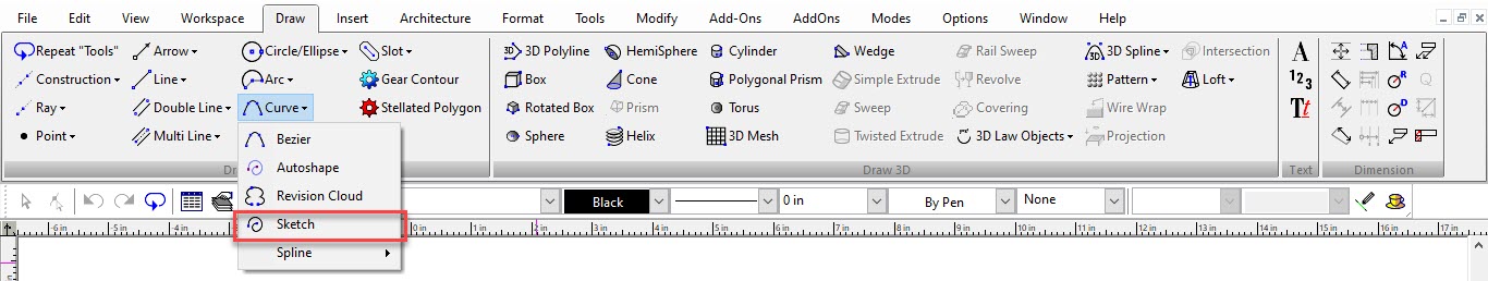
Creates a freehand drawing.
- Press and hold the mouse button to draw a freehand curve. Release the mouse when finished.
- As long as the tool is still active, you can continue drawing new curves.
Splines and Bezier Curves
These three tools each use a series of points to create a curve.
Spline by Control Points

Default UI Menu: Draw/Curve/By Control Points
Ribbon UI Menu:
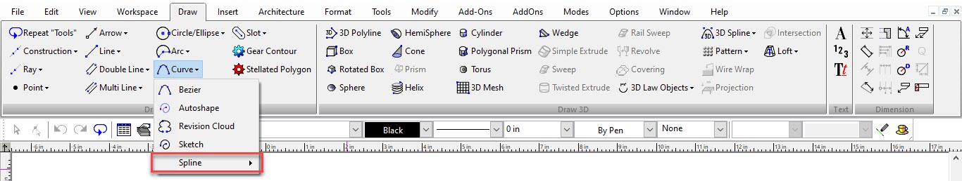
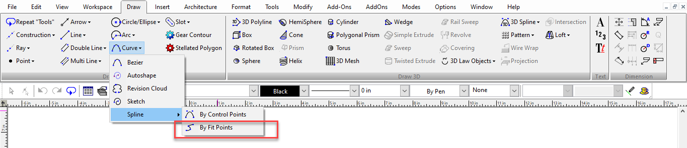
Spline by Fit Points

Default UI Menu: Draw/Spline by Fit Points
Ribbon UI Menu:
Bezier

Default UI Menu: Draw/Curve/Bezier
Ribbon UI Menu:
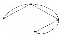
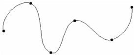
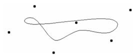
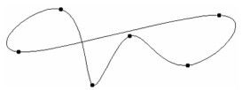
 For Spline by Control Points, the points act as a guide for the curve; the spline does not actually pass through all of the points. For Spline by Fit Points and Bezier, the curve does pass through each point. These two tools produce similar results; the main difference is the algorithm behind them, and how they are edited.
Note: To create splines in 3D, 3D Spline by Fit Points The three curves will be shown for this series of points:
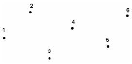
Select the control points in the desired order. You can also enter the length and angle between points in the Inspector Bar. After selecting the last point, select Finish from the local menu or press Alt+F. You can also double-click the last point.
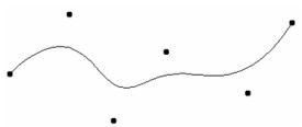
Spline by Control Points
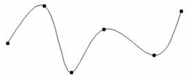
Spline by Fit Points
Bezier
If you want to close the curve, select Close from the local menu instead of Finish.
Closed Spline by Control Points
Closed Spline by Fit Points Once created, you can use the Edit Tool to change the shape of a spline and add knots. See Editing Splines and Bezier Curves
Tip: You can change a spline into a Bezier curve, and vice-versa, by opening the Properties window and editing the Curves page. If you change a Bezier curve into a spline, it will be a Spline by Control Points. You can also convert 2D objects into a Bezier curve.