Drawing Symbols
The AddOns menu contains several commonly-used symbols you can insert into your drawing. Most of these tools can also be found on the Special Tools toolbar, displayed by right-clicking in any toolbar and selecting Special Tools.
Drawing Markers
(Available in Platinum)
Default UI Menu: Architecture/Markers
Ribbon UI Menu:
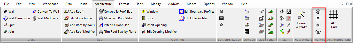
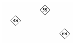
Use drawing markers to add a shape with text inside. You can choose between a circle, square, diamond, and hexagon. These tools can also be found on the Drawing Markers toolbar. 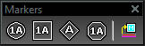 The marker is inserted with default text (1S, 2S, etc.).
You can edit the text on the General page of the marker's Properties. In addition, you can modify properties of either the shape or text by using the Selection Info palette. 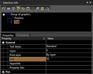
Geometric Tolerance
(Available in Platinum only)
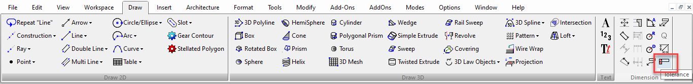
Default UI Menu: Draw/Tolerance
Ribbon UI Menu:
Tolerance is used to specify by how much a dimension can vary. Geometric tolerancing is a way to show maximum allowable deviations of form, profile, orientation, location, and run-out of a feature.
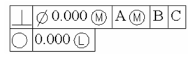
The first of two mandatory symbol frames contains a symbol that represents the geometric characteristic to which a tolerance is being applied, such as form, orientation, or run-out. Form tolerances control straightness, flatness, circularity, cylindricity, and profiles of lines and surfaces. The second mandatory frame contains the tolerance value. Where applicable, the tolerance value is preceded by a diameter symbol and followed by a material condition symbol. For a tolerance frame with two tolerance values, the second compartments contains the value of Tolerance 1 and is followed by a third, identical compartment that holds the value of Tolerance 2. Other (optional) compartments commonly contain a pair of symbols each. These are a datum reference letter and a material condition symbol.
- Select Draw | Tolerance tool.
- Click to place the insertion point of the tolerance.
- Click to set the angle of the tolerance insertion and to finish.
The Tolerance window provides controls for customizing the symbol frames. 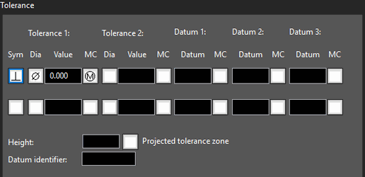 Sym: Select one of the available geometric characteristic symbols. Tolerance (#): Specify three parameters - the tolerance value and two symbols, diameter and material condition, preceding the value and succeeding it, respectively. The diameter symbol can be inserted by toggling the box preceding the tolerance value field. MC (Material Conditions): Relevant for features that can vary in size Maximum material condition (M or MMC): A feature contains the maximum amount of material stated in the limits. At MMC, a hole has minimum diameter, whereas a shaft has maximum diameter Least material condition (L or LMC): A feature contains the minimum amount of material stated in the limits. At LMC, a hole has maximum diameter, whereas a shaft has minimum diameter Regardless of Feature Size (S or RFS): A feature can be any size within the stated limits. Datum (#): A theoretically point, axis, or plane from which you make measurements and verify dimensions. Usually, two or three mutually perpendicular planes perform this task best. These are jointly called the datum reference frame. Specify one of three datum references - primary, secondary, and tertiary (A, B, and C). The datum reference can consist of a value and a modifying symbol Height Protected Tolerance Zone: Controls the variation in height of the extended portion of a fixed perpendicular part and refines the tolerance to that specified by positional tolerances. Enter a value in the data entry field. A projected tolerance zone symbol (P) can be inserted or discarded by toggling the box succeeding the height entry field. Use the Format page to set the parameters for the lines and text of the Tolerance. To edit a tolerance symbol, open its Properties window and click Tolerance.
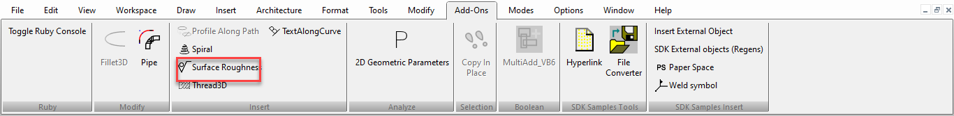
Surface Roughness
(Available in Platinum)
Default UI Menu: Draw/Surface Roughness
Ribbon UI Menu:
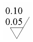
Use the Surface Roughness window to enter the symbol parameters. 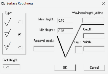
Click OK when finished, and locate the symbol in your drawing.
To edit a surface roughness symbol, open its Properties window object. Open the Other page, click Surface Roughness, and click Go To Page. This opens the original design window, in which you can change any symbol parameters.
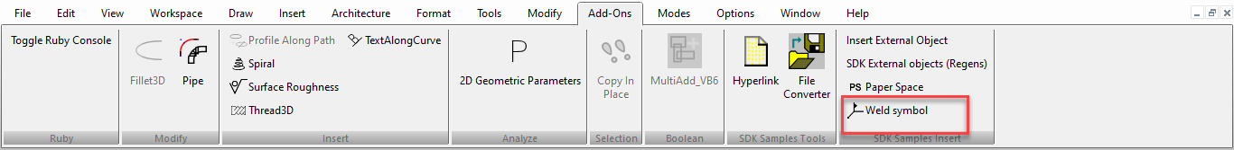
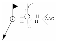
Weld Symbols
(Available in Platinum)
Default UI Menu: Addons/SDK Samples/Insert/Weld Symbol
Ribbon UI Menu:
Use the Weld Symbol window to enter the symbol parameters. 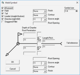
Click OK when finished, and locate the symbol in your drawing.
To edit a weld symbol, open its Properties window . Open the Other page, click Weld Symbol, and click Go To Page. This opens the original design window, in which you can change any symbol parameters.