Multi Line
(Available in all TurboCAD Variants)
Default UI Menu: Draw/Multi Line
Ribbon UI Menu:
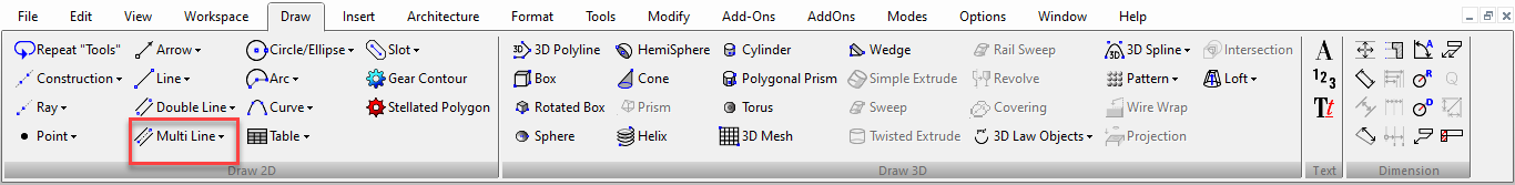
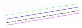
Tools for drawing multi lines and linear objects. Multi Line objects consist of two or more parallel lines, created as one object. The Multi Line tools are essentially similar to the Line tools, except that there are no tangent tools. You can display the Multi Line toolbar by right-clicking in any toolbar area and selecting Multi Line. 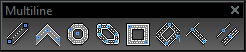
LTE Type Objects
In the LTE Workspace 2D tools behave with slight differences to standard TurboCAD methods.
- They allow use of dynamic input.
- They automatically drop when the action is completed, whereas standard TC tools continue until you change the tool.
- They have a Multiple option (local menu) that turns off auto-dropping for the individual tool.
- You can complete drop the tool by pressing the either the Enter or Space keys.
- You can re-activate the tool by pressing the Space Key again.
All LTE Workspace MultiLine tools work exactly as the equivelant TC tools except as noted in the above list.
Multi Line-Irregular Polygon

Default UI Menu: Draw/Multi Line/Irregular Polygon
Ribbon UI Menu:
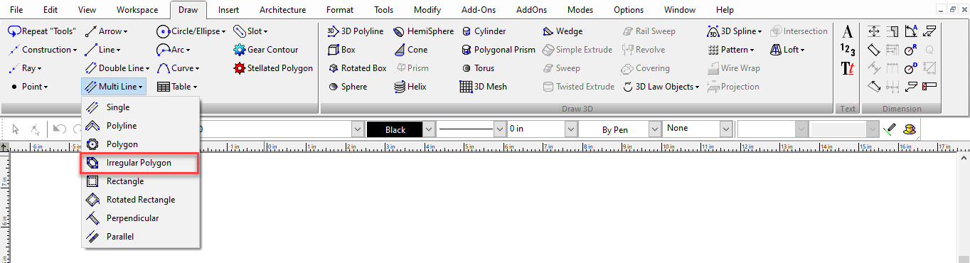
Creates a multi line polygon (closed) with irregular sides and angles. For the interaction, see Irregular Polygon 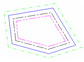
Multi Line-Parallel

Default UI Menu: Draw/Multi Line/Parallel
Ribbon UI Menu:
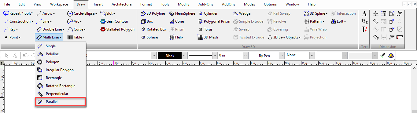
Creates a multi line parallel to a existing line. For the interaction, see Parallel 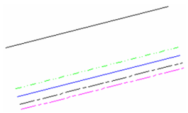
Multi Line-Perpendicular

Default UI Menu: Draw/Multi Line/Perpendicular
Ribbon UI Menu:
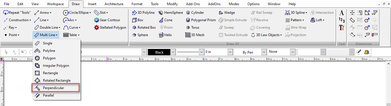
Creates a multi line perpendicular to an existing line. For the interaction, see Perpendicular 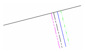
Multi Line-Polygon

Default UI Menu: Draw/Multi Line/Polygon
Ribbon UI Menu:
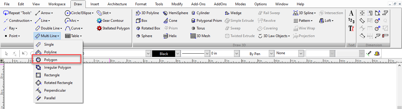
Creates a regular (equal-length sides) multi line polygon. For the interaction, see Polygon 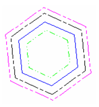
Multi Line-Polyline

Default UI Menu: Draw/Multi Line/Polyline
Ribbon UI Menu:
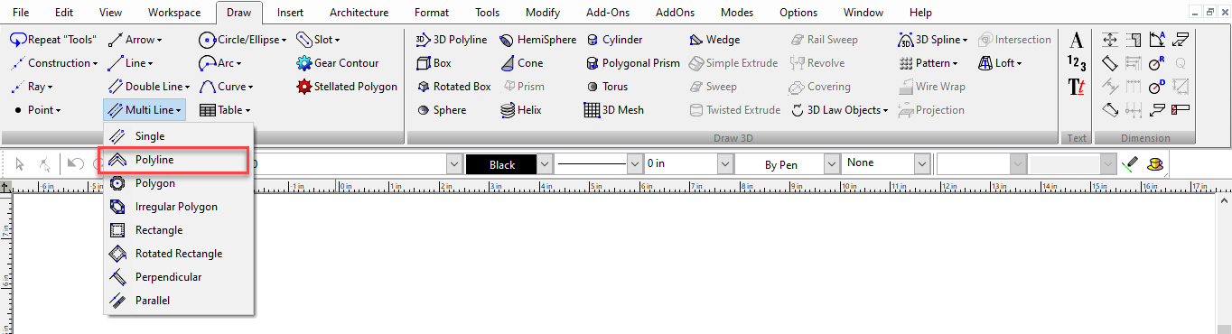
Creates a series of connected straight multi line segments (no arc segments) that comprise one object. For the interaction, see Polyline 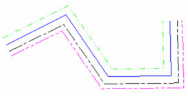
Multi Line Properties
Five pages of the Properties window contain options relevant to Multi Lines.
Multiline Properties
General properties for multi lines: 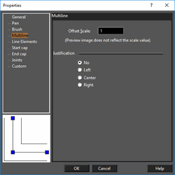
Offset Scale: Controls the overall width of the multi line. Justification: Sets the alignment of the multi line nodes. Left and right are determined by "facing" toward the multi line start point. No justification is the default; the line is aligned to a zero offset, relative to the line offsets defined in the Line Elements page. No Justification(Indicated line has zero offset) 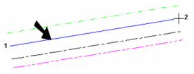
Left Justification 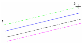
Center Justification 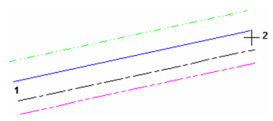
Right Justification 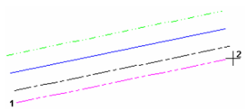
Dash and line width scaling: Determines whether the width of the multi lines will be scaled or will remain the same size when zoomed. This setting also applies to the size of the elements in the pen's dot-and-dash pattern. Device: The pen's width and pattern sizes are defined in device units (the monitor or printer). If you zoom the line width and pattern size will not change on the screen. World: The pen's width and pattern sizes are defined in by the drawing spaces units. If you zoom the line width and pattern size will change in accordance with the zoom factor. Device Width: The pen's pattern size is defined by the drawing spaces units, and pen's width is defined in device units (the monitor or printer). If you zoom the line patterns size will change, but the pen width size will not change.
Line Elements Properties
Properties for each line comprising the multi line. 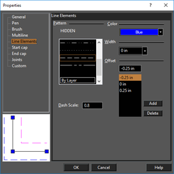
Pat. The exact look of each pattern depends on the setting of *Dash scale and width on the Multiline page. Dash Scale: The scale of the dot-and-dash pattern. Color: Select a color for each pen. By Layer and By Block are available. Width: Specify the width of each line. Zero width means one screen pixel, and will print at one unit of the printer's available resolution (a 300 dots-per-inch printer will print a zero width line at 1/300".) Offset: For each line, define its offset value. Use Add to create new lines, Delete to remove lines. 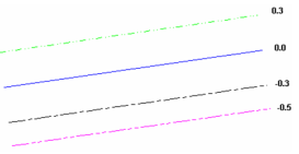
Start Cap and End Cap Properties
Start and end caps are used to close the ends of the multiline. The options are the same for start caps and end caps. 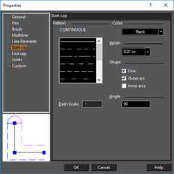
Joints Properties
Use joints to show breaks at each multi line segment. 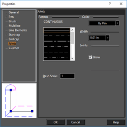 Show: Choose to show or hide the joints.
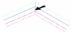
Note: Multilines can be used to trim objects, and can be trimmed themselves. However when trimming multilines you need to click near the center line of the trimmed multiline.
Multi Line-Rectangle

Default UI Menu: Draw/Multi Line/Rectangle
Ribbon UI Menu:
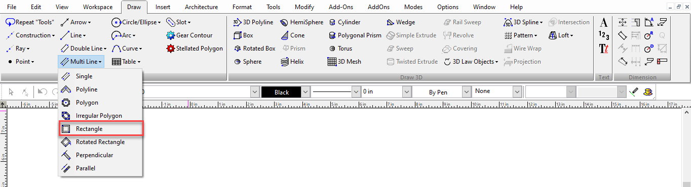
Creates an orthogonal multi line rectangle by defining two diagonally opposite corners. For the interaction, see Rectangle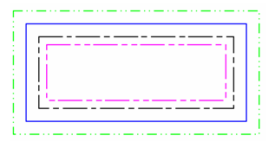
Multi Line-Rotated Rectangle

Default UI Menu: Draw/Multi Line/Rotated Rectangle
Ribbon UI Menu:
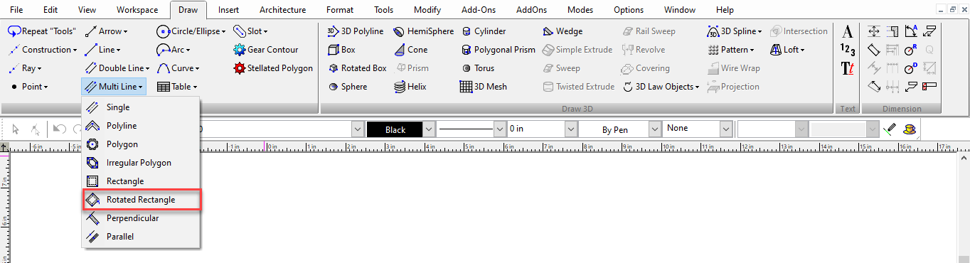
Creates a non-orthogonal multi line rectangle. For the interaction, see Rotated Rectangle 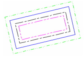
Multi Line-Single Line

Default UI Menu: Draw/Single
Ribbon UI Menu:
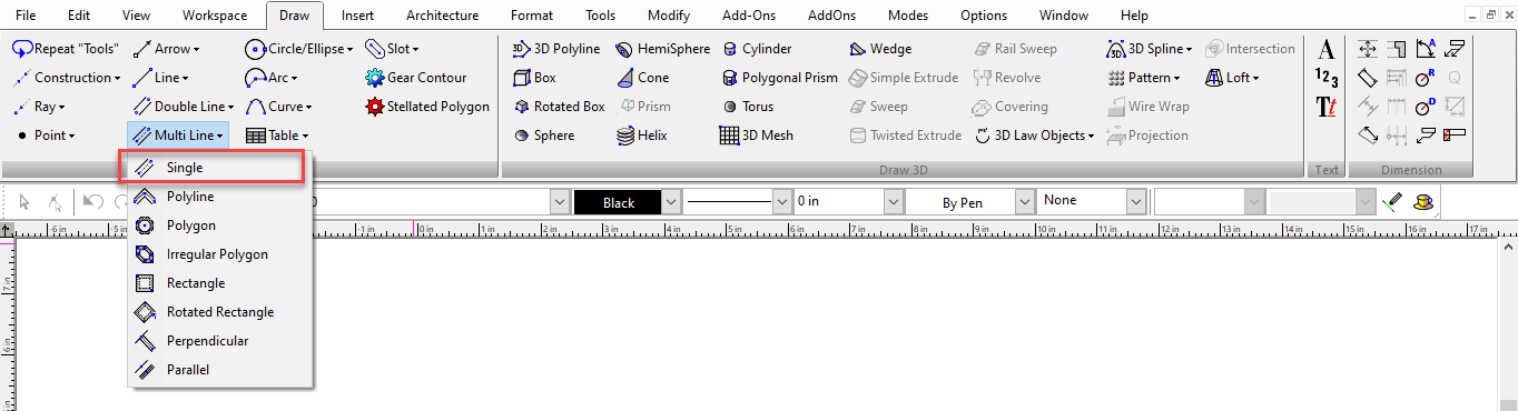
Creates one multi line. For the interaction, see Single Line