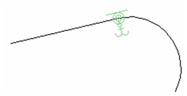
Constraining Geometry
(Available in Platinum and Professional)
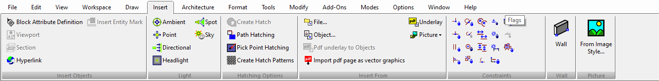
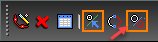
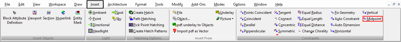
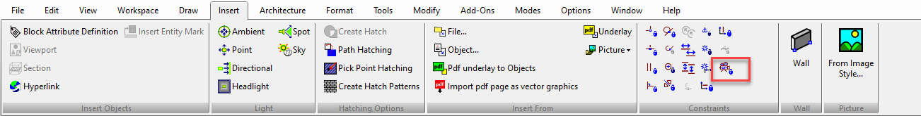
Default UI Menu: Constraints
Ribbon UI Menu:
Geometric constraints create positional relationships between 2D sketch objects. When used in conjunction with dimensional constraints , you can easily control and update objects and dimensions.
Note: These tools are used for constraining geometry after is has been created. If you want to automatically constrain geometry while it is created, make sure Auto Add Constraints* is active in the Inspector Bar.
You can display the Constraints toolbar by right-clicking in any toolbar area and selecting Constraints.
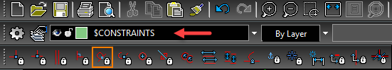
 Options for constraints can be found in Program Setup; see Constraints. When you activate a constraint, the active layer switches to "CONSTRAINTS." (For details on layers, see Snap Modes.)
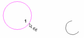
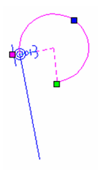
In the Inspector Bar, the Illuminate Suitable Entity option is active by default. This means that only those objects that can be selected for the constraint type will be highlighted when the cursor passes over them. For example, if you are using the Concentric* constraint, only arcs, circles, and ellipses will be highlighted and selectable.
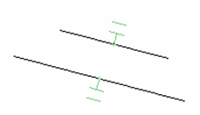
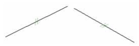
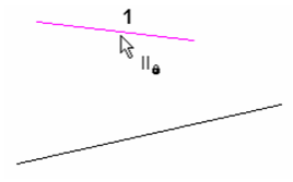
 When constraints are created, a constraint marker is attached to the constrained objects. This marker is on the CONSTRAINTS layer, in the layer's color. This example shows two lines that are constrained to be parallel.
Constraint markers can be selected like other objects. To remove a constraint, simply select and delete its marker.
Note: Constraints of selected objects can be viewed in the Selection Info palette. See Selection Info Palette
Auto Constraint
Default UI Menu: Constraints/Auto Constraint
Ribbon UI Menu:

Automatically applies multiple constraints to a selected set of objects. You can use this tool on compound objects like polygons and polylines; these objects are exploded before constraint are applied. This is a useful tool for applying a fast set of constraints on files created in previous versions of TurboCAD.
Note: If you want to constrain objects while they are created, and not after they are created, make sure Auto Add Constraints is active in the Inspector Bar.
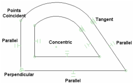
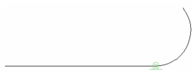
- Start with a polyline . Segment 1 is vertical, Segment 2 is horizontal. After Segment 3, switch to arc segments. Arc 4 is tangent to Segment 3, then close the polyline.
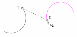
- Use Offset (see Offset) to make an outward copy of the polyline.
- Activate Auto Constraint, and in the Inspector Bar you can select which constraints you want to apply. The available constraints are Points Coincident, Parallel, Perpendicular, Concentric, Tangent, and Equal Radius. In this example, all are selected.
- Drag a selection box around all objects you want to constrain.
- Click Finish, or select it from the local menu.

Constraint symbols are displayed for every identified condition.
- You can test the constraints by editing one of the arcs. Use the Edit Tool to increase the radius. All constraints are maintained, but the offset is no longer uniform.
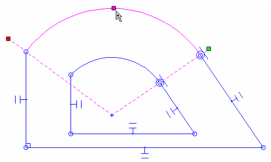
- Undo, and apply constraints to maintain the offset distance. Use Equal Distance to make the distance from Segment 3-4 equal to Segment 1-2. Do the same for Segment 5-6.
- Now if you edit either arc, the uniform offset is maintained.
- For another update, add a Connect constraint at the corner shown.
This changes not only the specified corner, but its offset corner as well.
Auto Dimension
Default UI Menu: Constraints/Auto Dimension
Ribbon UI Menu:
Automatically applies dimensions to a sketch.
Note: For detailed explanations of dimension tools. Auto Dimension is included in this section because it works best in conjunction with geometric constraints.
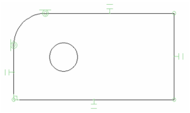
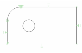
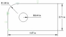
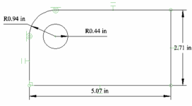
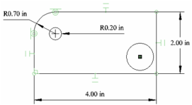
- Start with a rectangle and draw a small circle inside it. Fillet one corner (see Fillet).
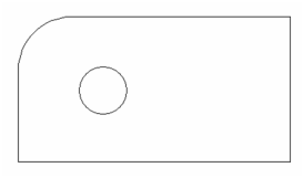
- Activate Auto Dimension, and in the Inspector Bar you can select which dimensions you want to identify and label. The available dimensions are Radius, Distance, Angular, and Parallel. In this example, all are selected.
- Drag a selection box around all objects you want to dimension.
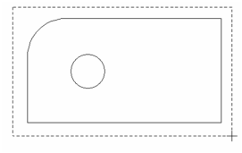
- Click Finish or select it from the local menu.
- This is the result - dimensions placed between all identified endpoints. This occurs when objects are not constrained. In particular, Points Coincident constraints are needed to reduce the number of auto dimensions.
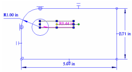
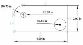
- Undo the dimensions. The easiest way to constrain the sketch is to use Auto Constraint (see Auto Constraint). The result in this case includes Tangent, Parallel, and Points Coincident constraints.
Note: You could also get the same constraints if you keep Auto Add Constraints active in the toolbar while you are creating geometry (rather than applying constraints after the geometry has been created).
- Use the same steps as before to apply auto dimensions. This is the result.
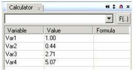
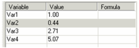
Dimensions created this way are assigned variables, which can be seen and edited in the dimensions's Properties (Format page), and in the Calculator Palette (see Calculator Palette - Variables Palette).
Change Chirality Constraint
Default UI Menu: Constraints/Change Chirality
Ribbon UI Menu:

This constraint tool provides two options for correcting tangency of arcs. This tool is useful if arc tangency becomes skewed when applying other constraint, or when editing causes an arc to flip.
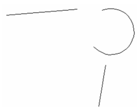
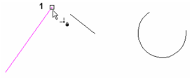
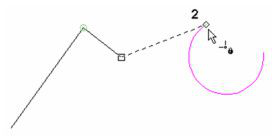
- Start with two lines and an arc like these.
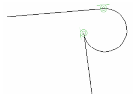
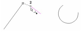
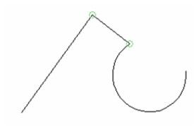
- Apply a Connect constraint (see Connect Constraint) at both ends of the arc so that it is tangent to, and trimmed to, both lines. If you want a filleted corner, this result does not have the desired arc tangency.
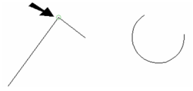
- The first option is Flip Arc, which changes the arc to its complement. Select this option . . .
- . . . and select the arc. The tangency along the vertical line is fixed, but is still incorrect along the horizontal line.
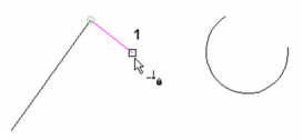
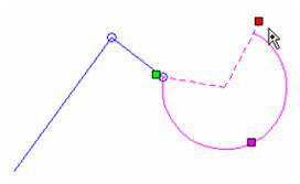
- The other option is Change Chirality, which changes the arc orientation. Select this option . . .
- . . . and select the arc.
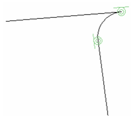
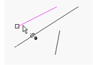
- Then select the line whose tangency you want to keep - the vertical line.
This is the result - a filleted corner.
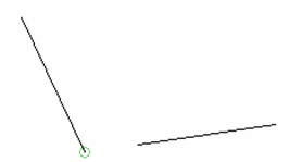
Coincident Constraint
Default UI Menu: Constraints/Coincident
Makes a vertex lie on another vertex, or on another object.
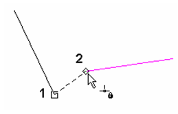
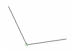
- Start with two lines. Activate the Coincident constraint and select the vertex you want to constrain.

- Select the line which you want the vertex to lie on.
The vertex moves to the line, or to a point on the line's theoretical extension.
If you constrain the vertex to another vertex . . .
. . . the two vertices will meet.
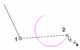
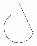
- This constraint is similar when using arcs and circles. Start with a line and a circle, and constrain the line endpoint to the arc endpoint.
The endpoints now meet.
- If you constrain the vertex to the arc itself . . .
. . . the line joins the arc at the tangent point.
Concentric Constraint
Default UI Menu: Constraints/Concentric
Ribbon UI Menu:

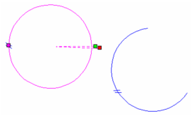
Makes two arcs/circles concentric - sharing the same center point. You can also use this tool to place a point or endpoint at the center of a circle or arc.
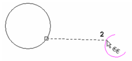
- Start with two arcs/circles. Activate the Concentric constraint and select the arc/circle you want to make concentric. This object will move to the second.
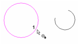
- Select the second arc/circle.
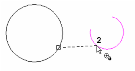
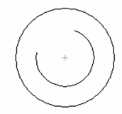
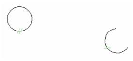
The first arc/circle moves, keeping its orientation, so that it is concentric with the second. The concentric constraint symbol (a plus sign) is added at the point of tangency.
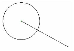
You can also use this tool on a point or line endpoint. Select a circle/arc and the point or endpoint. . .
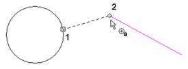
. . . and the circle/arc moves so that its center meets the endpoint or point.
Connect Constraint
Default UI Menu: Constraints/Connect
Ribbon UI Menu:

Moves, rotates, and trims arcs or lines so that the two selected endpoints will be coincident, and the objects will be tangent. If two lines are selected, they are connected with no regard to tangency, equivalent to the Points Coincident constraint.
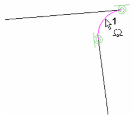
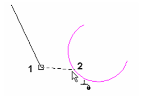
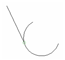
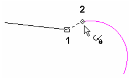
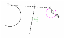
- Start with a line and an arc/circle. Activate the Connect constraint and select the endpoint of the line you want to connect to the arc.
- Select the endpoint of the arc to which the line will be connected.
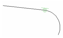
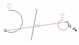
The line is moved, in an offset direction, so that it is tangent to the arc/circle. The arc is trimmed as needed. The connect constraint symbol is added at the point of tangency.

If you select the arc/circle first, and then the line . . .
. . . the arc moves and the unselected line endpoint remains in place.
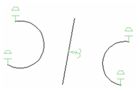
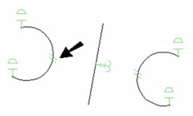
You can also select two circle/arcs. Select the arc you wish to move first . . .
. . .and the first arc moves to connect to the second arc.
Constraining Dimensions
You can use the Calculator Palette to assign constraints to dimensions, making them dependent on other dimensions or values.
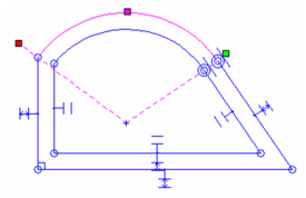
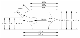
- Start with the same shape used to demonstrate Auto Dimension (see Auto Dimension), and apply Auto Constraints.
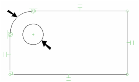
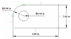
- Add one more constraint: make the fillet and the circle Concentric.
- In the Inspector Bar, make sure Auto Add Constraints is active. With this active, all dimensions you create will be placed as variables in the Calculator Palette. Otherwise, dimensions will be created but they cannot be constrained, or used as constraints for other dimensions.

The dimension types that can be constrained are Orthogonal, Parallel, Distance, Angular, Radius, and Diameter.
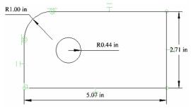
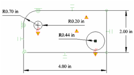
- Apply Auto Dimension, and you should get the following four dimensions:
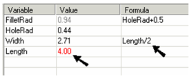
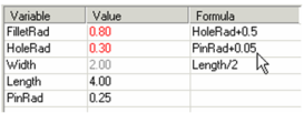
- Make sure the Calculator Palette is open (see Calculator Palette - Variables Palette). The four dimensions you created are listed here, with a variable name assigned to each.
- Select one of the dimensions, and the corresponding item is highlighted in the list.
Note: The dimension's variable can also be seen and edited in the Format page of its Properties.
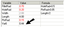
- Click the variable for the hole radius dimension, and change its name to something meaningful, like "HoleRad." Avoid using spaces in variable names.
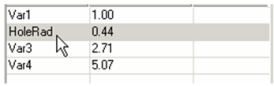
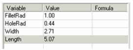
- Change the remaining variable names.
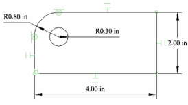
- One way to constrain a dimension is to base it on another dimension. For the fillet radius, click inside the Formula field and enter a formula that makes the fillet radius a set amount (0.5" in this example) larger than the hole radius.
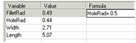
- Press Enter and the fillet radius updates based on the current value of the hole radius. The drawing updates as well.
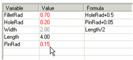
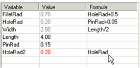
- You can also constrain dimensions to have an exact value, such as the value below for "Length." Width can also be constrained to be a constant factor (such as 1/2) of the length.
- You can also define a new variable independent of any of the current dimensions. "PinRad" is the radius of the pin that fits in the hole, and is assigned a numerical value.
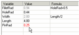
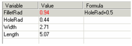
- Once "PinRad" is defined, the hole radius can be made to a set amount larger than the pin.
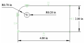
- If "PinRad" is updated, then both "HoleRad" and "FilletRad" are automatically updated.
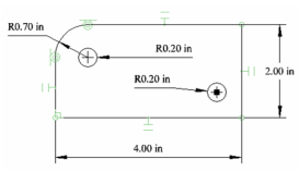
- You can also constrain new dimensions, as long as Auto Add Constraints is active. Create another circle, and inside this circle add a point . Make the point and the circle Concentric.
Note: The point is added because a circle's center point is not identified as an object; a physical point must be placed there.
- Add a Radius dimension to the new circle, and its variable appears in the constraint list.
- If you try placing an Equal Radius constraint on the two circles, you will receive an error message:
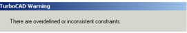
- When you click OK, the problem dimensions are indicated.
This occurs because the second circle is considered to already have a set radius, once it is dimensioned. So constraining it to be equal to the first circle is contradictory. You could have assigned the Equal Radius constraint before assigning the dimension.
- Undo, and use a dimensional constraint to set the radius, making it equal to "HoleRad."
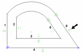
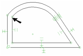
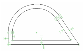
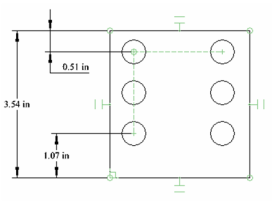
Constraining Pattern-Copied Objects
This section refers to objects copied in patterns (lines, linear arrays, radial arrays), using the Copy Entities tools . When you copy objects in a pattern, you can use Auto Constraints and dimension variables to control spacing, angles, etc. This example uses a circle copied into a linear array.
- Before you begin, make sure Auto Add Constraints is active in the Inspector Bar.
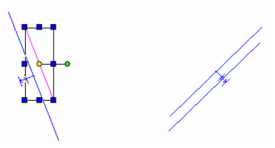
- Create a rectangle and add a small circle. The rectangle should have parallel and coincident constraints assigned automatically.
- Select the circle and use Fit Array Copy to copy the circle into a grid. See Fit Array Copy
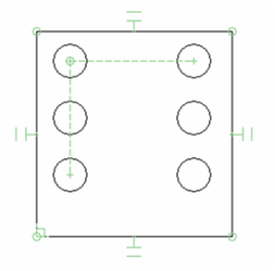
- Assign some Orthogonal dimensions as shown.
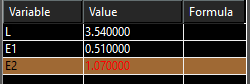
- Open the Variables palette (F2) and the dimensions should be shown, identified by a variable. In this example, the variables were assigned names (L, E1, E2).
Note: For more information on working with variables, see Calculator Palette - Variables Palette
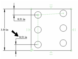
- Create a formula so that the two edge dimensions will be equal. In this case, the variable E1 was used as the formula for E2.
The dimensions update, and the spacing between copied objects remains constant. However, in this case, the linear array does not have a 90 degree angle.

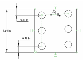
- Used the Horizontal constraint on the bottom edge of the rectangle.
- To fix this, activate the Parallel constraint and click first the array (horizontal) constraint line, then the top line of the rectangle. Repeat if necessary to make the array perpendicular vertically.
Now the array is perpendicular again.
Equal Distance Constraint
Default UI Menu: Constraints/Equal Distance
Ribbon UI Menu:

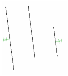
Sets the distance between two lines to the same between two other lines. Sets of lines are also made parallel.
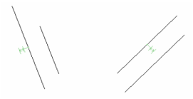
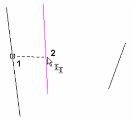
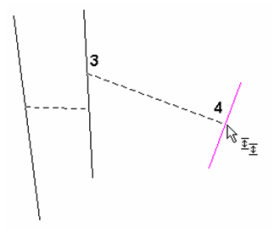
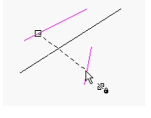
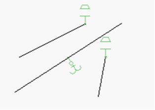
- Start with four lines. Activate the Equal Distance constraint and select the first line in the first set.
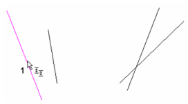
- Select the second line in the first set. This establishes the distance for the next set.
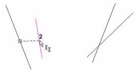
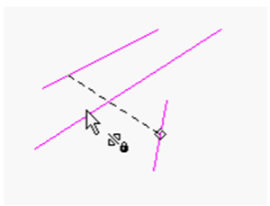
- Select the first line in the second set.
- Select the second line in the second set.
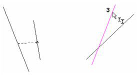
The first set and second set of lines are made parallel. The distance between the lines in the second set matches the distance in the first set.
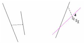
- If you edit any line, the equal length constraint will be maintained.
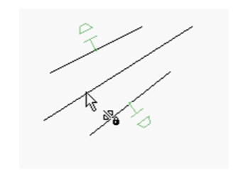
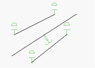
- You can also apply this constraint to a row of lines or points. Select the first and second lines.
- The third line is the same as the second, then select the fourth.
The result is three lines, parallel and separated by the same distance.
Equal Length Constraint
Default UI Menu: Constraints/Equal Length
Ribbon UI Menu:

Makes the first selected line have the same length as the second line.
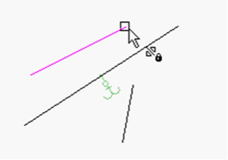
- Start with two lines. Activate the Equal Length constraint and select the line whose length you want to change.
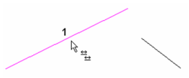
- Select the line whose length you want to assign to the first line.
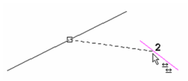
The first line's length changes to match the second. The equal constraint (an equal sign) appears.
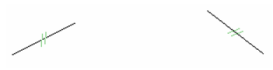
- If you edit either line, the equal length constraint will be maintained.
Equal Radius Constraint
Default UI Menu: Constraints/Equal Radius
Ribbon UI Menu:

Makes the first selected circle/arc have the same radius as the second circle/arc.
- Start with two circles/arcs. Activate the Equal Radius constraint and select the arc whose radius you want to change.
- Select the arc whose radius you want to assign to the first arc.
The first arc's radius changes to match the second. The equal constraint (an equal sign) appears.
- If you edit either arc, the equal radius constraint will be maintained.
Fix Geometry Constraint
Default UI Menu: Constraints/Fix Geometry
Ribbon UI Menu:

Locks an object or endpoint at its current coordinate, preventing the object or point from moving when constraints are applied.
Note: The fixed object or point can be moved while editing geometry, but will not move when constraints are placed upon it.
- To fix an object, activate the Fix Geometry constraint and select the object you want to fix.
The anchor symbol indicates that the object is fixed.
- Now if you apply a constraint, such as Parallel in this case, the non-fixed line will move, regardless of the selection order.
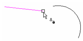
- For another example of this tool, start with a line and arc and apply a Connect constraint
- The result is that the line maintains its orientation and is tangent and trimmed to the arc.
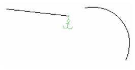
- Undo this constraint, and apply a Fix Geometry constraint to the line's endpoint.
Now the anchor symbol is attached to the endpoint.
- Now apply the Connect constraint. The endpoint stays fixed, and the orientations of the line and arc are modified.
- If you edit the line or arc, such as changing start or end angles, the fixed point will not move, and the other objects will move or rotate accordingly.
Horizontal-Vertical Constraint
Default UI Menu: Constraints/Horizontal, Constraints/Vertical
Ribbon UI Menu:

Forces a line to be horizontal or vertical.
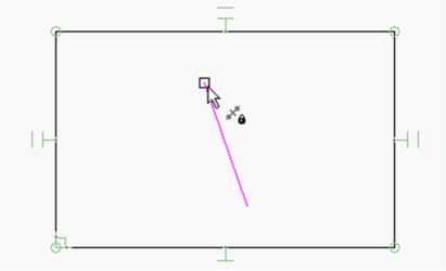
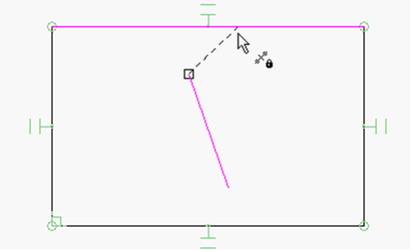
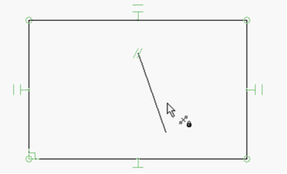
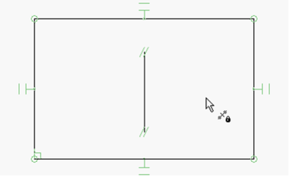
- Start with a line.
- Activate the Horizontal or Vertical constraint.
- Click the line, which becomes horizontal or vertical.
Midpoint Constraint
Default UI Menu: Constraints/Midpoint
Ribbon UI Menu:
Align a point or the end of a line with the midpoint of a selected line.
- Start with a line and a constrained rectangle. Activate the Midpoint constraint and select the end of the line line you want to align to the midpoint of the side of the rectangle.
- Select the side of the rectangle to align to its midpoint.
The end of the line aligns with the midpoint of the rectangles side.
- Repeat the procedure with the other end of the line and the opposite side of the rectangle.
Parallel Constraint
Default UI Menu: Constraints/Parallel
Ribbon UI Menu:

Makes the first selected line parallel to the second selected line.
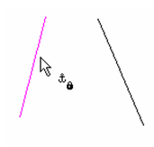
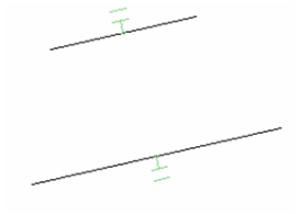
- Start with two lines. Activate the Parallel constraint and select the line you want to be made parallel.
- Select the line to which you want the first line to be parallel.
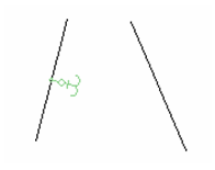
The lines are parallel, and the parallel constraint symbol is added to both lines.
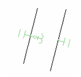
- If you edit either line, the parallel constraint will be maintained.
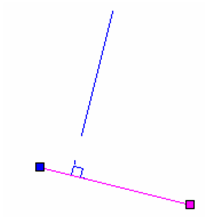
Perpendicular Constraint
Default UI Menu: Constraints/Perpendicular
Ribbon UI Menu:
Makes the first selected line perpendicular to the second selected line.
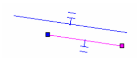
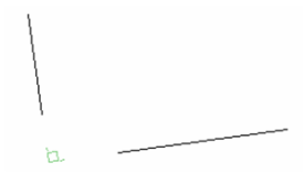
- Start with two lines. Activate the Perpendicular constraint and select the line you want to be made perpendicular.
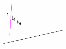
- Select the line to which you want the first line to be perpendicular.
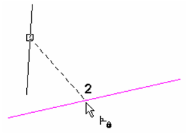
The lines are perpendicular, and the perpendicular constraint symbol is added at the point where the lines, or their extensions, meet.
- If you edit either line, the perpendicular constraint will be maintained.
If you apply this constraint to lines that do not intersect . . .
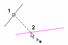
. . . the perpendicular constraint symbol will appear along the extension of one or both lines.
Points Coincident Constraint
Default UI Menu: Constraints/Points Coincident
Ribbon UI Menu:

Moves a point or endpoint to another point.
- Start with two lines and an arc.
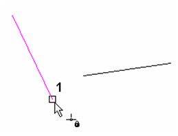
- Activate the Points Coincident constraint, and click an endpoint of the first line.
- Click an endpoint of the second line.
The first line is moved so that the two points are coincident. The length and orientation of the line is maintained, and a constraint symbol appears at the coincident point.
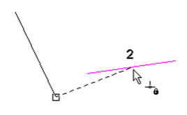
- Create another constraint between Point 1 . . .
- . . . and Point 2 - an endpoint of the arc.
Both lines move, and their lengths and orientations are maintained.
- If you edit any of the objects, such as the arc in this case, the coincident constraint will be maintained, and the other objects will keep their size and orientation (when possible).
Symmetric Constraint
Default UI Menu: Constraints/Symmetric
Ribbon UI Menu:

Makes two objects, or object endpoints, symmetric with respect to a symmetry axis.
- Start with three lines - one of which is the symmetry line. In some cases the symmetry line will move as a result of this constraint, so if you want it to remain in place, fix it with a constraint such as Fix Geometry.
- Activate the Symmetric constraint and select the first line.
- Select the second line.
!
- Finally, select the symmetry line.
The first two lines are now symmetric with respect to the third.
- You can also use this constraint on endpoints. Select Vertices 1 and 2, then select the symmetry line.
!
The lines themselves keep their orientation, but their endpoints are symmetric.
- To make both lines completely symmetric, apply the Symmetric constraint to the other two endpoints.
- This constraint can also be used on circles and arcs. If you select two arcs (not at their endpoints) . . .
!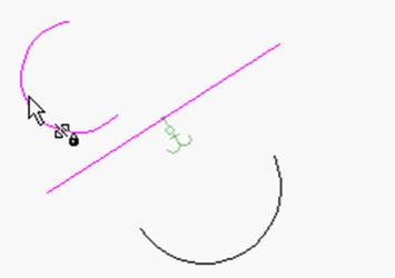
... they will become symmetric and have equal radii.
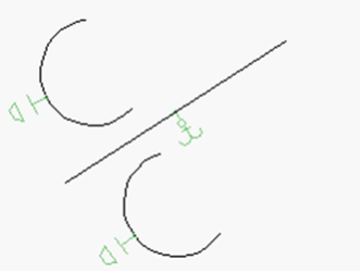
- Like with lines, you can apply the Symmetry constraint at both sets of endpoints. First the upper endpoints . . .
- . . . then the lower endpoints.
The result is that both sets of endpoints are symmetric, but the orientations of the arcs are still different, because they have different radii.
- You can make the arcs completely symmetric by adding an Equal Radius constraint.
Note: You could get the same results if you apply three Symmetric constraints - one to the arcs themselves, and one for both sets of endpoints.
Tangent Constraint
Default UI Menu: Constraints/Tangent
Ribbon UI Menu:

Makes an arc or circle tangent to another arc or circle, or to a line.
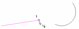
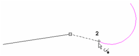
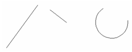
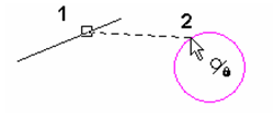
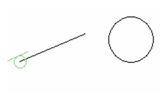
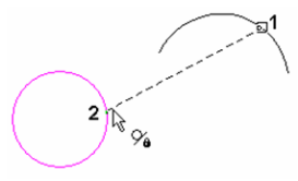
- Start with a line and an arc/circle. Activate the Tangent constraint and select either object (when one object is a line, the selection order does not matter).
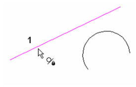
- Select the other object.
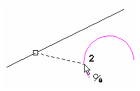
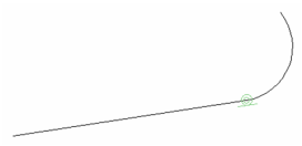
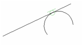
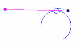
The line is moved, in an offset direction, so that it is tangent to the arc/circle. The tangent constraint symbol is added at the point of tangency.
- If you edit either object, the tangent constraint will be maintained.
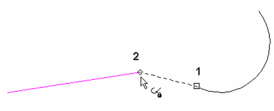
If you apply this constraint to a line whose offset will not meet the arc/circle . . .
. . . the line is moved so that its extension is tangent to the circle.
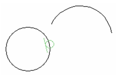
You can also make two arcs/circles tangent to one another. In this case, the first selected object will move to meet the second selected object. If the arc does not meet the other arc/circle . . .
. . . the arc is moved so that its extension is tangent to the arc/circle.
Constraint Animation
Default UI Menu: Constraints/Animation
Ribbon UI Menu:
The Constraint Animation tool enables the user to animate dimensions in TurboCAD drawings. With the help of animation, the user can visualize the boundary of moving parts in a mechanical design. The user can play the animation in a loop, pause the animation to verify different parameters, play again from the same place, increment or decrement step by step the animation, choose the delay in animations and also select the animation steps to suit his/her needs.
Make sure that you select the dimension from the drawing. To see if the dimension is a valid one, you can see if it is has been added to the Calculator palette. You can also select the variable from the Calculator palette in order to animate it
To apply Animation:
- Draw any 2D object with Auto- Constraints enabled
- Then, add any dimension type on that drawn 2D object
- Select Animation Constraint from the menu
- Click on the valid dimension added to the 2D object
The Constraint Animation Dialog then opens
- Set the Constraint Parameters and then press Play to view the animation.
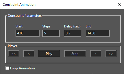
Start: Define the starting dimension length, distance, size, or angle for the animation
End: Defines the ending dimension length, distance, size, or angle for the animation
Steps: Defines the number of steps/jumps required from start to end points
Delay: Defines the time delay per step
Play: Plays the animation
Stop: Stops the animation
Loop Animation: Loops the animation back to the Start when reaching the End