Editing 3D Objects using SI
Note: For general information on this palette, see Selection Info Palette You can use the Selection Info palette to edit properties and parameters of 3D objects, taking into account the order in which the objects were created. Objects must be created as solids; surface objects cannot be edited this way (see 3D Properties). In addition to seeing what objects were used in which operations, you can also edit certain properties of these operations: Fillet Edges and Chamfer Edges: add or subtract affected edges, modify the chamfer length or fillet radius. Boolean operations: Change the size or location of the original objects combined in the Boolean operation. Shell: Change the open faces, set inward or outward shelling, modify the shell thickness. Imprint: Change the type of imprint, add a draft angle, and change the fillets and chamfers at the edges. See Editing Imprint Parameters After you make a change to any operation, all subsequent operations will update to reflect the change.
Warning: Facet Deform operations cause the edited objects to be deleted from the editing history.
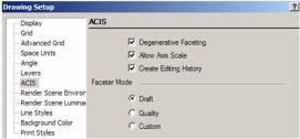
In order for object history to be recorded, you must check Create Editing History in the ACIS page of Drawing Setup (Options / ACIS).
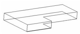
- This example started with a Simple Extrude, based on a linear polyline. Make sure that the Use compound profile option is turned on, otherwise the profile will not be linked to the resulting extrusion.
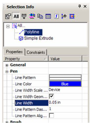
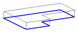
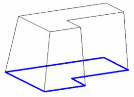
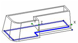
- Highlight Polyline and change its color and line weight.
Now the polyline is easily differentiated from the solid.
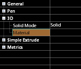
For the Simple Extrude, you can edit all parameters that are available in its Properties window. For example, the 3D category has an option to change the object into a surface object and to set the object's Material.
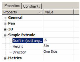
- Under Simple Extrude, increase the Height and add a slight Draft In (out) Angle.
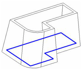
The solid is now higher with drafted walls.
- Use Fillet Edges to round one edge Then use Shell Solid to shell this shape, leaving the top face open (see Shelling Solids.)
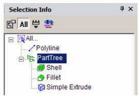
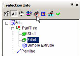
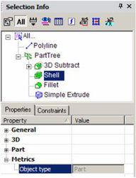
In Selection Info, the Extrude, Fillet and Shell operations are listed under "Part Tree."
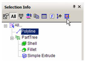
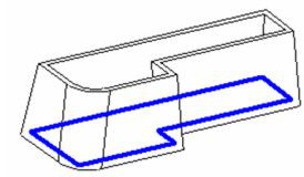
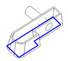
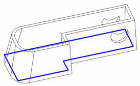
- The Simple Extrude is based on the polyline, and changing the polyline will update the solid. Highlight Polyline and click Select.
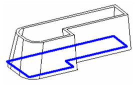
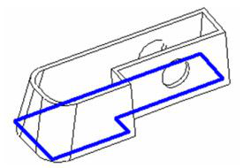
- Scale the polyline in Select Edit mode to make it longer. The solid shape, as well as the fillet and shelling update automatically.
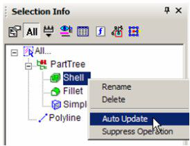
- Subsequent operations do not have to update automatically. To disable this, right-click on "Shell" and select.
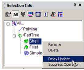
Note: If you click Suppress Operation, the operation will be removed from part history, though its item will still remain in the list. You can bring the operation back into the model by selecting Unsuppress Operation.
- To edit the fillet, highlight it and select.
- Edit in Place enables you to return to the original operation and make changes. Click another edge for filleting. You could also change parameters such as the fillet radius.

- Select Finish to update the operation. The shell has not updated.
- To update the shell, right-click t and select.
Now the shell reflects the new filleted edge.
- For the next operation, create a cylinder, with its workplane located on one of the vertical faces.
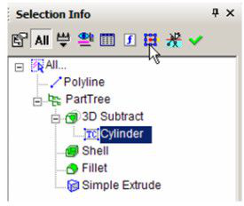
- Then use the Boolean operation 3D Subtract to remove the cylinder from the shelled solid. (See 3D Subtract.)
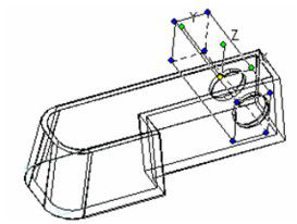
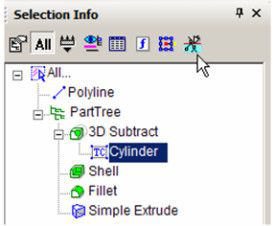
- The 3D Subtract operation is now listed. If you expand it, you can see the Cylinder on which it is based. Highlight the cylinder, and click Select.
- Move the cylinder, which in turn updates the 3D Subtract operation.
- For another way to edit the cylinder, select Edit Content.
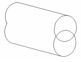
- The cylinder is now the only object in the drawing area, and any changes will modify the operations currently based on the cylinder. Make a copy of the cylinder so that they overlap.
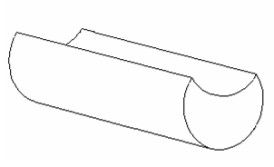
- Then use 3D Subtract to get this shape:
- When finished, click Finish Editing Content.
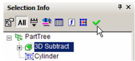
The entire solid is updated, based on the modified cylinder.
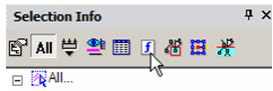
- For one of the solid operations, open Metrics. It only informs you that the object is a solid, as opposed to a surface.
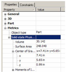
- Click Show Physical Metrics.
This displays properties such as volume, area, center of gravity, and moments of inertia.
**XClip

(Available in all TurboCAD Variants)
Default UI Menu: Modify/Clip/XClip
Ribbon UI Menu:
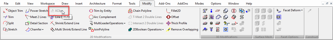
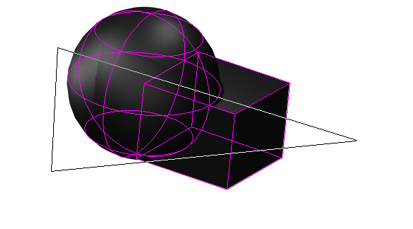
The XClip tool creates a cropped/clipped display of a selected external reference or block reference based upon a selected boundary. You can use any circle, or closed polyline consisting of only straight segment as a boundary.
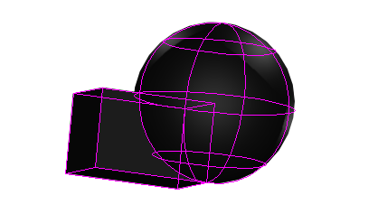
- Select an xref or a block or a group of xrefs or blocks.
- In the local menu select the Rectangular/Polygonal option.
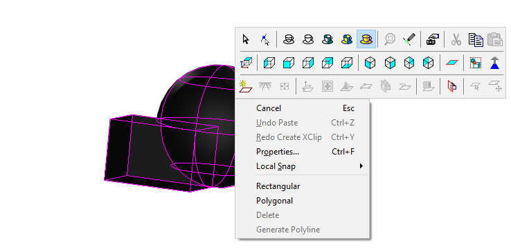
- Draw the desired cutting area.
4.Press Finish from Local menu or Inspector bar.
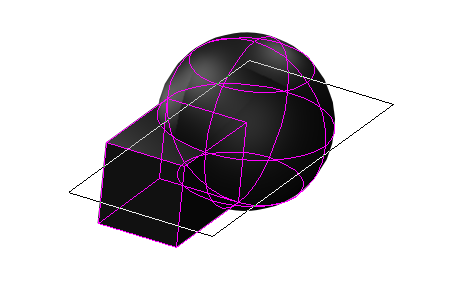
In Local Menu,If you click the "Generate Polyline" option,it will create a polyline of area you have cutted.
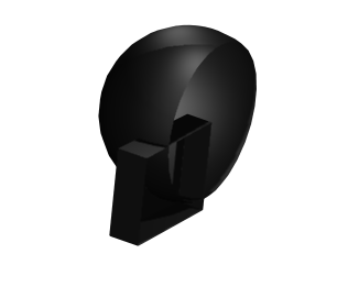
A cropped version of the xref or block is created. the original xref or block insertion is destroyed. The xclip and the selected boundary are not associative, so updating the boundary does not update the xclip. If the xref/block contained 3D object these objects are shown as "hollowed" whether they are surfaces or ACIS solids. Xclipping does not create new geometry for the clipped entities so the missing faces are simply not displayed. In this regard xclips are not like booleans. Regardless of the current UCS, the clip depth is applied parallel to the clipping boundary.
XClip Properties
XClip properties provide added control for how xclips are displayed.

Display only result: if this option is unchecked the clipping boundary will be ignored, and all of the geometry of the clipped blocks or xrefs will be displayed. Enable front clip: If this option is selected the xclip will clip everything in the clipped entities above a specified height. Front clipping always occurs parallel to the original clip boundary. Front Clip: Sets the height for front clipping. Enable back clip: If this option is selected the xclip will clip everything in the clipped entities below a specified height. Front clipping always occurs parallel to the original clip boundary. Back Clip: Sets the depth for back clipping. In the following picture the the xclip has a Front Clip of 12in. and a Back Clip of 1in.