Examining the 3D Model
Once the model contains one or more 3D objects, there are several ways to change the way you see the model.
Camera Movements
(Available in Platinum, Professional and Deluxe)
Default UI Menu: View/Camera/Camera Turn, View/Camera/Camera Slide
Ribbon UI Menu:
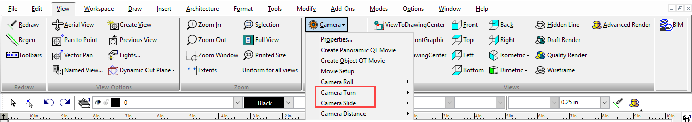
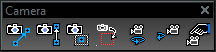
Incremental controls for adjusting the camera, and therefore your view of the model. As the camera moves through space, the visible objects will seem to move in the opposite direction of the camera motion. These commands can be accessed via the Camera toolbar. You can also display the Camera Tools toolbar by right-clicking in any toolbar area and selecting Camera Tools.
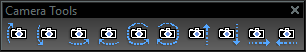
Camera Turn Up: Turns the camera up.
Camera Turn Down: Turns the camera down.
Camera Turn Right: Turns the camera to the right.
Camera Turn Left: Turns the camera to the left.
Camera Rotate Right: Rolls the camera clockwise.
Camera Rotate Left: Rolls the camera counter-clockwise.
Camera Up: Moves the camera up.
Camera Down: Moves the camera down.
Camera Right: Moves the camera to the right.
Camera Left: Moves the camera to the left.
Camera Objects
(Available in Platinum, Professional and Deluxe)
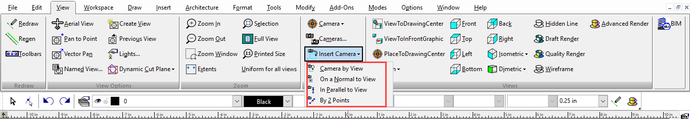
Default UI Menu: View/Camera/Insert Camera
Ribbon UI Menu:
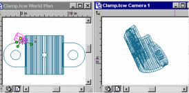
Camera objects are used to create and save views with specific parameters. The view for each camera object can be displayed in a separate window. Each new camera is assigned a name by default (Camera 1, Camera 2, etc.) but this name can be changed. You can display the Camera toolbar by right-clicking in any toolbar area and selecting Camera.
The difference between camera objects and saved views is that saved views do not open in separate windows, and do not include any additional parameters, such as render mode.
Note: You can also create and manipulate camera objects, and group cameras into camera sets, via the Design Director.
Camera Object by View
Inserts the camera at the center of the view, so that the camera view is the same as the current model view. The properties of this camera are those of the default camera representing the current view, described in the Camera page of the Camera Properties The camera object itself is not visible in the current window, and a separate view window will not be created, since you are already looking at the camera view.
Camera Object Normal to View

Inserts the camera perpendicular to the current model view. The camera will face the same way as Camera by View, but can be placed anywhere.
Camera Object Parallel to View

Inserts the camera on a plane parallel to the current model view. The first point places the camera, and the second point defines its direction.
Camera By 2 Points

Inserts the camera by picking two points. The first point places the camera and the second point defines its direction.
Camera Object Views
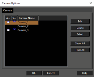
To display the view seen by the camera object, you can create a separate view window. To create a view window, click the
 icon for the relevant camera. The icon is used to show or hide the camera indicator. You can also use this dialog to edit and delete camera objects.
Select: Selects the highlighted camera in the drawing. This option is useful when the drawing is large, and you are unable to find the camera in the screen.
icon for the relevant camera. The icon is used to show or hide the camera indicator. You can also use this dialog to edit and delete camera objects.
Select: Selects the highlighted camera in the drawing. This option is useful when the drawing is large, and you are unable to find the camera in the screen.
Show All: Makes all camera objects visible.
Hide All: Hide all camera objects. To display all view windows, select Window / Cascade or Window / Tile.
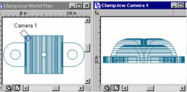
If you change the direction of a camera in one window, the views in any attached windows will update accordingly. If you use other view controls in an attached window, the camera position will be changed.
Camera Object Properties
Double-click a camera object.
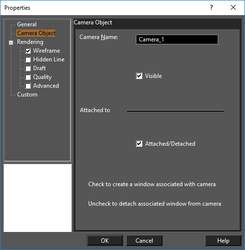
Visible - Check this box to display the camera object indicator in the view window. Attached / Detached - Check this box to create a new drawing window containing the camera view. Updates to the camera will update the view. Unchecking the box will disconnect the window from the view, so that updates to the camera will not affect the view.
Camera Sets
A camera set is a group of cameras, which can be handy if you want to set rendering, perspective, and visibility parameters for multiple cameras. Camera sets are created and manipulated in the Design Director.
QuickTime Movies
(Available in Platinum, Professional and Deluxe)
Default UI Menu: View/Movies Ribbon UI Menu:
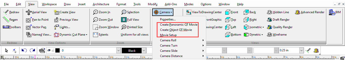
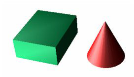
If the model is rendered by LightWorks, you can export the scene to a QuickTime movie format. This format does not create an actual animated movie, rather it exports to a format in which you can rotate and view objects from different angles. The QuickTime player can be downloaded for free from www.apple.com. There are two types of QuickTime movies: Panoramic: Constructed from a series of images taken from a fixed viewpoint. You can rotate around the viewpoint and look in all directions. Object: Constructed from a series of images taken from different angles. You can rotate the objects in any direction, to view all sides. Before you can create a movie, the scene must be in Perspective mode, which is set in the Camera Properties (View / Camera / Properties).
Also, the LightWorks rendering must be one of the following modes: Flat (Draft rendering) Gouraud (Draft rendering) Phong (Draft rendering) Preview (Quality rendering) Full (Quality rendering)
Creating a Movie
Panoramic QT Movie

Create Object QT Movie

- Create the 3D model and view it in Perspective mode.
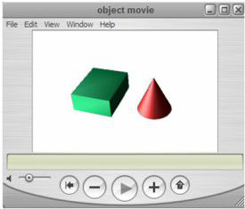
- Create either the Panoramic or Object movie. You are asked for a file name, and you are notified when the movie is created.
- Play the movie using the QuickTime Viewer. With either movie type, you can pan or rotate the scene by holding the left mouse button and moving the mouse.
Movie Setup
Opens the QuickTime Movie Setup window.
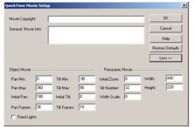
To display the lower section of the window, click the More button. Movie Copyright and General Movie Info: Identifying information about the movie. Object Movie properties Pan Min, Pan Max: Limits of horizontal pan position, in degrees. Initial Pan: The starting horizontal angle, in degrees, for when the movie is first opened. Pan Frames: The number of frames to generate between the Pan Min and Pan Max positions. With the default value of 36, frames are rendered every 10 degrees. Tilt Min, Tilt Max: Limits of vertical pan position, in degrees. Initial Tilt: The starting vertical tilt angle, in degrees, for when the movie is first opened. Tilt Frames: The number of frames to generate between the Tilt Min and Tilt Max positions. With the default value of 19, frames are rendered every 10 degrees. Fixed Lights: As the camera moves around an object, the lights will stay fixed relative to the camera. This gives the effect that the camera is static and the object is rotating, which may look more natural in some cases.
Note: Object movie files contain a large number of frames, and can therefore take a long time to create. With the default values of 36 pan frames and 19 tilt frames, 684 frames will be created.
Panoramic Movie properties Initial Zoom: Defined by a value between 0 and 100. Slit Number: The number of individual images that should be rendered. The default value should be used for all but advanced users; setting this value too low could result in distortion, and setting it too high can result in minimal quality gain. Width Scale: Movie width will be set as follows: Movie width = (Width Scale)* (Width / 2) - Width. When you increase the movie width, be aware that rendering time and movie file size also increases. Width, Height: The dimensions of the movie viewing window.
The Camera

(Available in Platinum, Professional and Deluxe)
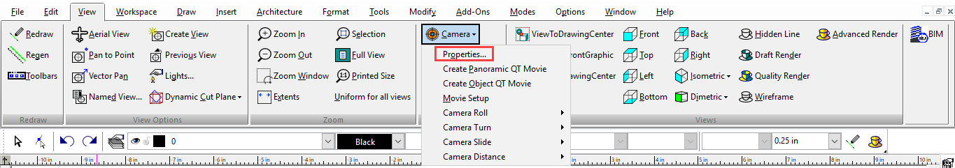
Default UI Menu: View/Camera/Properties
Ribbon UI Menu:
In 3D space, you can view a model from any point. TurboCAD uses the concept of a "camera" - the camera represents your eye as you view the current scene. You can easily use the standard orthogonal and isometric views, but camera tools enable you to view from any angle. The current model view contains a default camera, placed at the center of the screen, facing into the model.
Note: While "camera" means the perspective of the current view, "camera object" is something different. Camera objects are created to save and display multiple views, or views with specific parameters.
Camera Properties
Controls the position and target of the camera, as well as rendering controls. For the rendering properties,
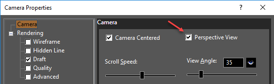
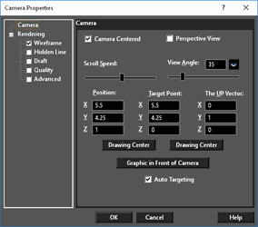 Camera Centered: Enables the camera to turn around its own center when you use the Camera Turn tools . When not checked, the camera will turn around the
Target Point. Scroll Speed: The speed of the camera movement.
Perspective View: The visual effect of a perspective projection is similar to that of photographic systems and of the human visual system. The size of the perspective projection of an object varies inversely with the distance of that object from the center of projection.
Note: When using Perspective View, objects cannot be located or moved beyond the horizon. Select Display Horizon to display the horizon, in order to better orient yourself to the space.
View Angle: The degree of perspective foreshortening. The view gets wider as the setting gets larger.
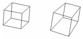
Standard view and perspective view Position: The physical location of the camera. Drawing Center: Assigns the target point coordinates as the drawing center. The drawing center is always the geometric center of all the objects in the drawing.
Note: You can also access this view by selecting View / Camera / Look to Drawing Center.
Target Point: The point that the camera faces.
Drawing Center: Moves the camera to the current drawing center.
The UP Vector: Indicates which way is up for the camera. A positive Z value rotates the camera up; a negative Z value rotates the camera down.
Graphic in Front of Camera: Select the object closest to the desired view center, and the target point is attached to that object.
Note: You can also access this view by selecting View / Camera / Look to in Front Graphic.
Auto Targeting: Sets the center of rotation on the object closest to the center of the screen (the default camera position). This is relevant when moving objects using the keyboard and mouse (such as Shift + right mouse button).
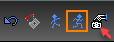
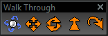
Walk Through Tools
(Available in Platinum, Professional and Deluxe)
Default UI Menu: View/Walk
Ribbon UI Menu:
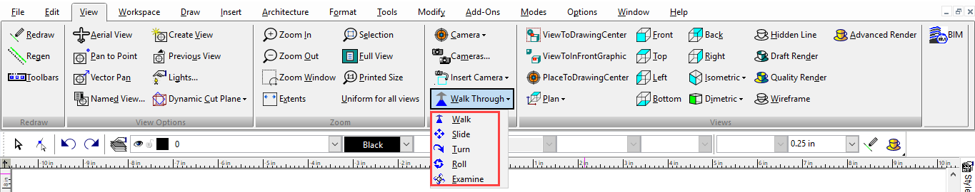
Dynamic (moving) controls for moving the camera. These commands can be accessed through the Walk Through toolbar. You can display the Walk Through toolbar by right-clicking in any toolbar area and selecting Walk Through.
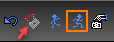
Examine
Ctrl + Right mouse button Views the model from different angles. Drag the mouse to the right to see the left side of the object. Drag downward to see the top of the object.
Slide
Ctrl + Shift + Right mouse button Moves the camera along a plane parallel to the screen. You can move the camera up, down, left or right, but not forward or backward. Drag the mouse straight up to move the viewpoint upward, drag to the left to move it left. If you drag the mouse along an angle, the viewpoint will move along the corresponding angle. It's important to remember that the camera will move in the same direction as the cursor, which means that the Model Space will appear to move in the opposite direction.
Roll
Shift + Right mouse button or Ctrl with the arrow keys. Rotates the camera around the axis that passes through the camera. This tool will rotate the viewpoint either clockwise or counterclockwise. Drag the mouse to the left to rotate the viewpoint clockwise; drag to the right to rotate counterclockwise. Vertical movement of the mouse will behave identically to the Walk control.
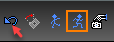
Walk
Simulates walking around on the current plane. This is a handy way to walk through a 3D house model, for example. Positions the camera on the current horizontal plane, also known as the viewplane. Moving the mouse forward or backward moves the viewpoint in the corresponding direction. Left or right movement turns the camera in the corresponding direction. To move the viewpoint forward, drag the cursor toward the top of the screen. To move backward, drag toward the bottom of the screen. If you drag diagonally upward toward the left or right, the viewpoint will move forward at an angle; if you drag diagonally downward to the left or right, the viewpoint will move backward at an angle.
Note: This tool will move forward or backward only when the Perspective View option is checked on the Camera page of the Camera Properties.
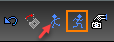
Turn
Rotates the camera around its center. This changes the angle of the viewpoint without relocating the camera. The viewpoint angle can be changed upward or downward. The viewpoint angle can be also be changed to the left or right. To turn the viewpoint right, drag the mouse to the right of the screen. To turn downward, drag toward the bottom of the screen. As with Slide, the viewpoint will move in the same direction as the cursor. This will have the effect of moving the view of the model on the screen in the opposite direction of the cursor motion.
Local Menu Options
While using the Walk Through controls, there are several options available on the local menu and Inspector Bar. Undo Move: Returns the view to the position in which the current mode was invoked.
 Straighten: Returns the view to a level orientation.
 Discrete Movement: Limits camera motion. When on, the camera will only move when the mouse is moving.
 Continuous Movement: Allows the camera to move as long as the left mouse button is held down. The camera movement will be in the direction the mouse was dragged. This is the default option.
 Camera properties: Opens the Camera Properties window.