Wall Tools
Default UI Menu: Architecture/Walls
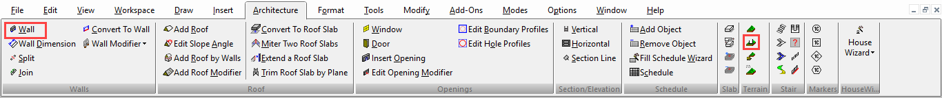
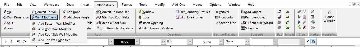
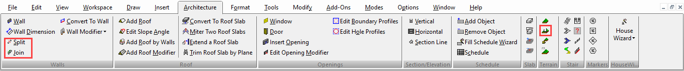
Ribbon UI Menu:
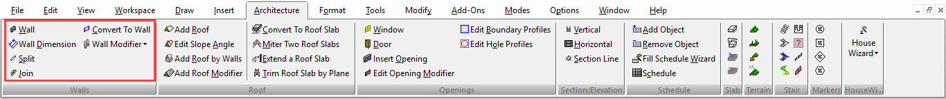
The Wall tools help you quickly work out a wall design, by creating smart objects. Walls heal at intersections, and they can take block insertions that automatically align correctly. The typical sequence to create a floor plan starts with a wall layout. When the walls have been drawn, insert doors, windows and/or openings. After that, you can adjust the wall layout by moving or rotating any wall. When you adjust a wall, the walls that are attached to it will adjust to it. Any inserted doors, windows, and openings also adjust.
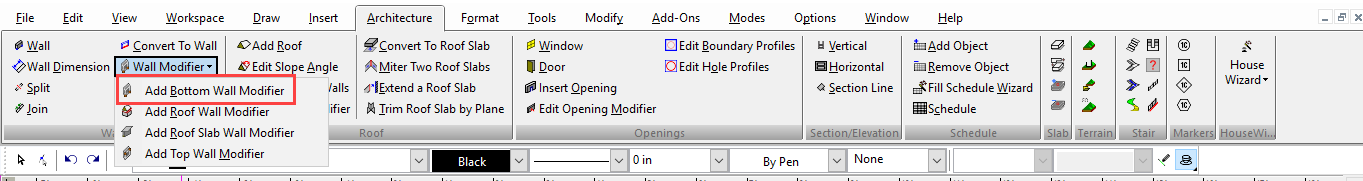
Add Bottom Wall Modifiers
(Available in Platinum)
Default UI Menu: Architecture/Walls/Add Bottom Wall Modifier
Ribbon UI Menu:
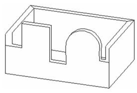
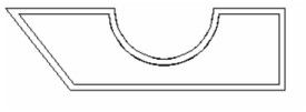
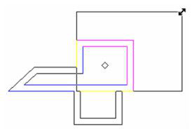
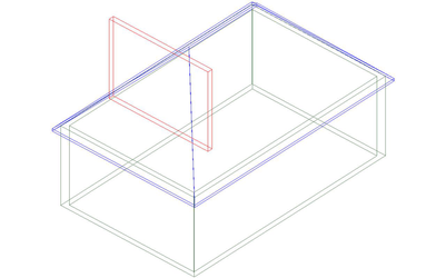
Enables you to change the bottom height of a wall by trimming or extending it to a single-line object. The object can be a line, arc, or polyline. It must be at least as long as the wall, and cannot extend below the bottom of the wall. In addition, it must lie in the same workplane as the wall.
Note: The way to assign height to a wall is to open its Properties to the 3D page and enter a Height.
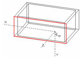
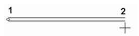
- Set the workplane to the wall you want to modify. The easiest tool is By Facet.
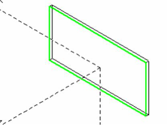
- Create the object you want to use as a modifier. Be sure that the object meets or extends past the wall ends.
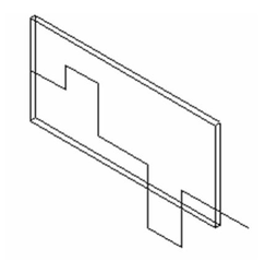
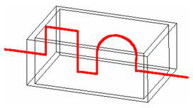
- Activate Add Bottom Wall Modifier, select the wall to modify, and select the 2D modifier. The wall is trimmed or extended to meet the modifier.
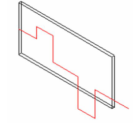
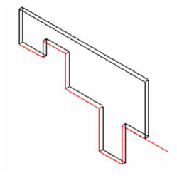
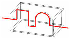
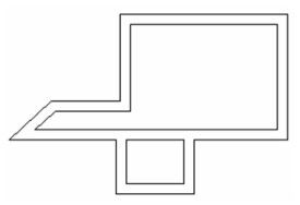
The results may be easier to see in Hidden Line mode.
Note: If the modifier length is insufficient, you can edit it. The modifier will be applied once it reaches the required length.
If you add another Bottom modifier, it will cancel the effect of the previous one. You can use Top and Bottom modifiers on the same wall.
Add Top Wall Modifiers
(Available in Platinum)
Default UI Menu: Architecture/Walls/Add Top Wall Modifier
Ribbon UI Menu:
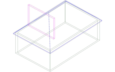
Enables you to change the top height of a wall by trimming or extending it to a single-line object. The object can be a line, arc, or polyline. It must be at least as long as the wall, and cannot extend below the bottom of the wall. In addition, it must lie in the same workplane as the wall.
Note: The way to assign height to a wall is to open its Properties to the 3D page and enter a Height.
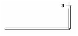
- Set the workplane to the wall you want to modify. The easiest tool is By Facet.
- Create the object you want to use as a modifier. Be sure that the object meets or extends past the wall ends.
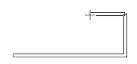
- Activate Add Top Wall Modifier, select the wall to modify, and select the 2D modifier. The wall is trimmed or extended to meet the modifier.
The results may be easier to see in Hidden Line mode.
Note: If the modifier length is insufficient, you can edit it. The modifier will be applied once it reaches the required length.
If you add another Top modifier, it will cancel the effect of the previous one.
Convert to Wall
(Available in Platinum)
Default UI Menu: Architecture/Walls/Convert to Wall
Ribbon UI Menu:

Converts single-line objects into walls. This is useful for creating curved walls.
- Select the object to convert. You can select lines, arcs, circles, polylines, etc. Multiple objects can be selected.
- Select Finish from the local menu or Inspector Bar. The wall is created with the default thickness, but you can modify its Properties,
Note: The way the wall is created in relation to the original object depends on the Reference parameter in the Wall page of the Properties window.
Editing Walls
(Available in All TurboCAD Variants)
The Edit Tool can be used to move or resize walls.

Note: For details on this tool,
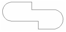
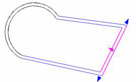
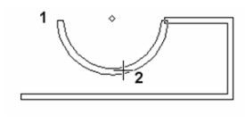
- This example shows a set of walls with one arc segment. Activate the Edit Tool and click the segment you want to change.
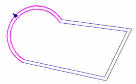
- Select Edit Nodes.
- With this options, you can move the node at either end. If you click and drag the arrow, you are constrained to the line of the wall.
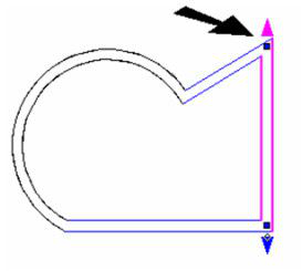
- If you click and drag a node, you can move it anywhere.
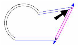
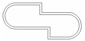
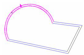
- Switch to Edit Segments.
- Now you can move the entire wall, constrained to its current orientation
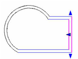
- You can also change arc segments with the Edit Tool.
- With Edit Segments, the arc center stays the same and the arc radius changes.
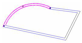
- With Edit Nodes, the arc endpoints stay the same.
Inserting 2D Blocks in Walls
(Available in All TurboCAD Variants)
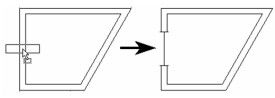
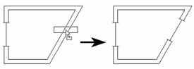
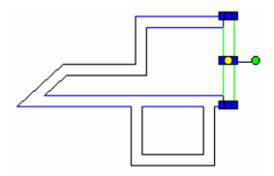
When a 2D block is inserted into a wall, it rotates to align itself with the wall. The direction of the rotation depends upon the direction in which the wall was drawn; the top of the block will align to the right side of the selected wall. (The right side is determined by facing the wall's start point from the end point.)
Note: This method of inserting blocks applies to 2D blocks, and 2D (plan) representation of walls. To create walls and doors that you can see in 2D as well as 3D,
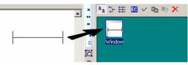
- Create the 2D representation of the desired insertion (door, window, etc.). Create a block from these objects. You can do this by selecting the objects and dragging them into the Blocks Palette, or by selecting Format / Create Block.
For more information on blocks,
- Drag the block from the Blocks Palette onto the wall at the point where you want to insert it. The block will automatically align itself with the wall, and a cutout will be created.
Inserting Walls
(Available in All TurboCAD Variants)

Default UI Menu: Architecture/Walls/Wall
Ribbon UI Menu:
Creates segments of double lines that represent wall layouts. The difference between this tool and the Double Line tools is that walls automatically heal at corners and intersections. In addition, you can attach walls to existing walls which will also heal.
Justification of walls:
There are four types of justification Left, Center, Right and Baseline. Justification allows you to select the alignment of every new wall. You can select the options from local menu or inspector bar.
- Select two points to draw the first wall segment.
Tip: Use Shift to activate Ortho mode if you want to draw horizontal and vertical walls.
- Select the endpoint for the next wall segment. The corner is automatically healed; no intersection lines are shown.
- Select more wall endpoints as needed.
-
To add a circular wall segment, select Arc Wall* from the local menu or Inspector Bar and.
-
To create the arc segment, first select the endpoint, then select a point along the circumference.
- To return to linear walls, turn off Arc Wall. Continue selecting wall endpoints. Select Finish from the local menu or Inspector Bar. If you want to close the wall, select Close from the local menu or Inspector Bar.
Any wall segment can be deleted or moved like any other object.
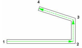
You can now choose to enter an Angle (which is absolute in relation to the world coordinates) or a Relative Angle which is the angle from the immediately previous segment (arc or line). For the Wall tool, the Relative Angle is always enabled. At the first state we draw a straight wall (the relative angle is enabled)
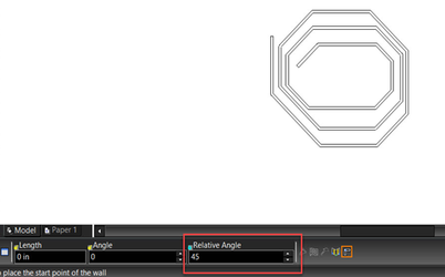
The Relative Angle is also enabled with Curved Walls.
Walls have two aspects which define how they interact with one another: Linking and Healing. Linking means that walls are associative (attached). If you move or modify a wall, walls that are linked to it will modify themselves to remain attached. Healing means that the intersection of walls is cleaned to show a joint without overlapping elements.
Attaching Walls
Any wall you add to an existing wall will be automatically healed at their intersections.
- Click inside an existing wall at the point where you want to add another wall.
- Select segment endpoints.
-
If you extend a segment to an existing wall, this intersection will be healed as well.
-
If you extend a segment using the T-Meet tool or Meet 2 Lines tool into an existing wall, this intersection will be healed and linked.
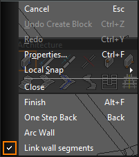
Link Wall Segments
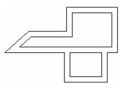
The Link Wall Segments (local menu) option controls whether walls become linked as they are drawn. It is on by default, but If it is turned off walls will not become linked. You can tell if a wall is linked by selecting it. Any other segments linked to that wall will be highlighted. Since walls automatically linked when you draw then in proximity this option can be useful for drawing a wall close to another wall without having them link. For example, this can be useful for drawing cubicle walls in an office setting.
Drop Link between Wall Segments
You can break the link between any two walls segments.
- Select the two segments
- Right click to open the local menu and select Drop Link.
Moving Walls
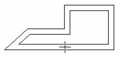
To move a single wall, select it as you would any other object and use the Select Edit tools to move, scale, or rotate it. Moving a wall will affect its adjacent walls.
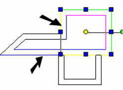
- In Select mode, select the wall you want to move. To select multiple walls, use Shift or drag a selection window.
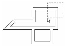
In addition to the walls you selected, adjacent walls are marked in blue, so that you will see all affected walls before performing the edit.
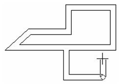
- Use the Select Edit tools to move, rotate, or scale the selected wall or walls.
The affected walls extend or shrink to meet the new walls, but their orientation does not change. If the walls contain inserted windows, door, or other blocks or openings, they will adjust as well.
Roof Wall Modifier
(Available in Platinum)
Default UI Menu: Architecture/Walls
Ribbon UI Menu:
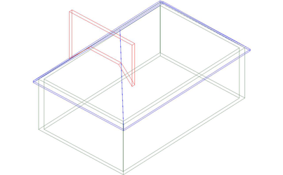
Enables you to extend the top or bottom of a wall to meet the roof (this does not work with Roof Slabs). This is especially important if you have edited the Slope angle of a roof so that you have an open gable end.
Note: The way to assign height to a wall is to open its Properties to the 3D page and enter a Height.
-
Select the Roof Wall Modifier tool.
-
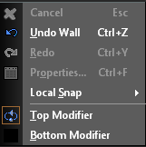
From the Local menu choose either
- Select the wall you want to modify..
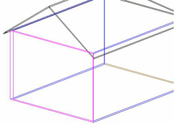
- Select the roof to which you want the wall to extend.
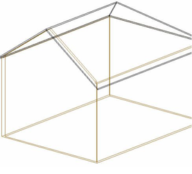
- The wall will now extend to the roof.
 Top/Bottom Wall Modifiers will override Roof Wall Modifiers, and Roof Wall Modifiers will override Top/Bottom Wall Modifiers, depending upon the sequence in which they are added.
Splitting and Joining Walls
(Available in Platinum)
Default UI Menu: Architecture/Walls/Split, Architecture/Walls/Join
Ribbon UI Menu:
Splits a wall into two separate walls, and joins split walls into one wall. This tool works on straight walls only, not curved walls. To use the Split tool:
-
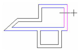
Select the wall you want to split.
-
Position the cursor where you want to split the wall, and click to split.
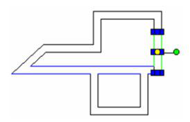
- Because walls automatically heal, you will not be able to see the split (unless you use end caps). If you select one of the walls, you can see that the original wall was split.
To use the Join tool:
- Select the two segments you want to join. The walls are combined into one wall.
Note: Most standard Modify tools, such as Trim, Split, and Meet 2 Lines, will work with walls.
Wall Dimension
(Available in Platinum)
Default UI Menu: Architecture/Walls Dimension
Ribbon UI Menu:
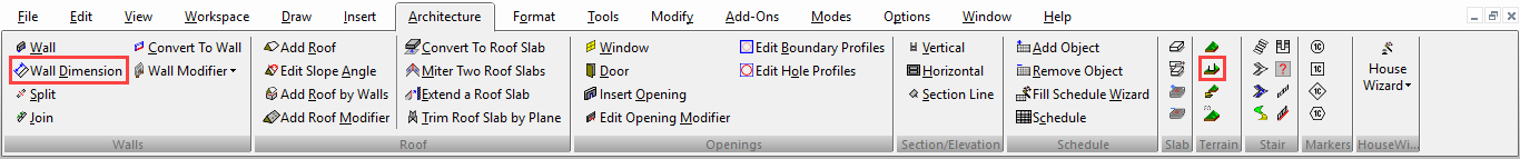
Specialized architectural dimensioning tool for walls. This tool is used in conjunction with the Style Manager.
Wall Properties
(Available in All TurboCAD Variants)
Options for wall alignment, thickness, end caps, and direction.
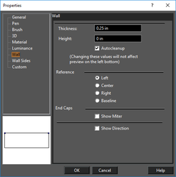 Thickness: The thickness of the wall (distance between the double lines).
Height: The vertical height of the wall.
Autocleanup: This option sets whether the wall will automatically cleanup (heal) at intersection with other walls. This can be useful if you want to show the overlap between walls
Show Miter to close the ends of a wall.
Show Direction: Displays a wall's direction, from its start point to its end point. This is useful when defining end caps, and when assigning materials to different sides of the wall.
Thickness: The thickness of the wall (distance between the double lines).
Height: The vertical height of the wall.
Autocleanup: This option sets whether the wall will automatically cleanup (heal) at intersection with other walls. This can be useful if you want to show the overlap between walls
Show Miter to close the ends of a wall.
Show Direction: Displays a wall's direction, from its start point to its end point. This is useful when defining end caps, and when assigning materials to different sides of the wall.
Note: The location of the directional arrow depends on which Reference option was used (Left, Right, or Center.)
Wall Side
(Available in Platinum and Professional)
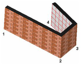
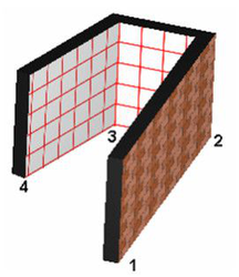
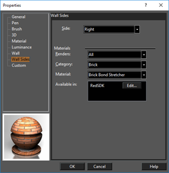 Side: Left and Right depend on the wall's direction, assuming you are standing at the start point and facing the end point. To show the directional arrow, check Show Direction on the Wall page of the Properties.
For details on materials,
In this example, the walls were created in the order shown. The Right sides of the walls have a brick material, and the Left sides have a grid pattern.
Side: Left and Right depend on the wall's direction, assuming you are standing at the start point and facing the end point. To show the directional arrow, check Show Direction on the Wall page of the Properties.
For details on materials,
In this example, the walls were created in the order shown. The Right sides of the walls have a brick material, and the Left sides have a grid pattern.