Copying Objects
(Available in all TurboCAD Variants)
Default UI Menu: Modify/Copy
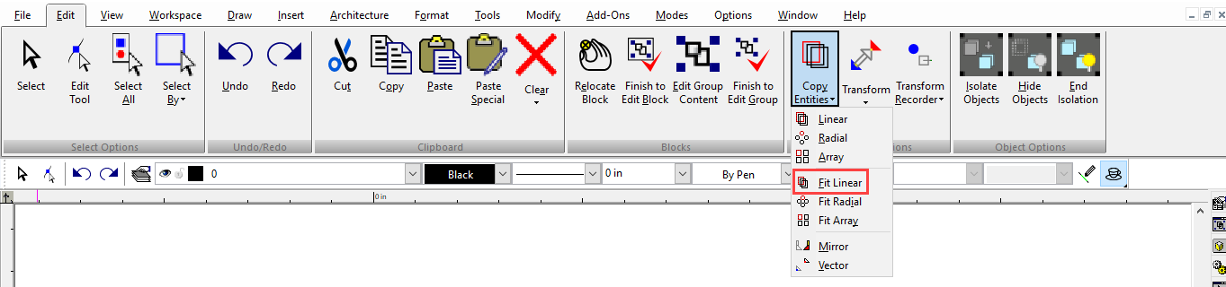
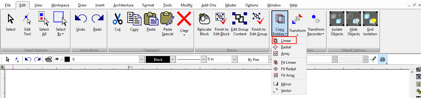
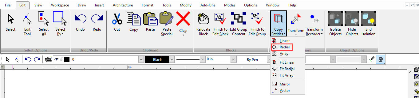
Ribbon UI Menu:
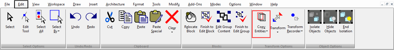
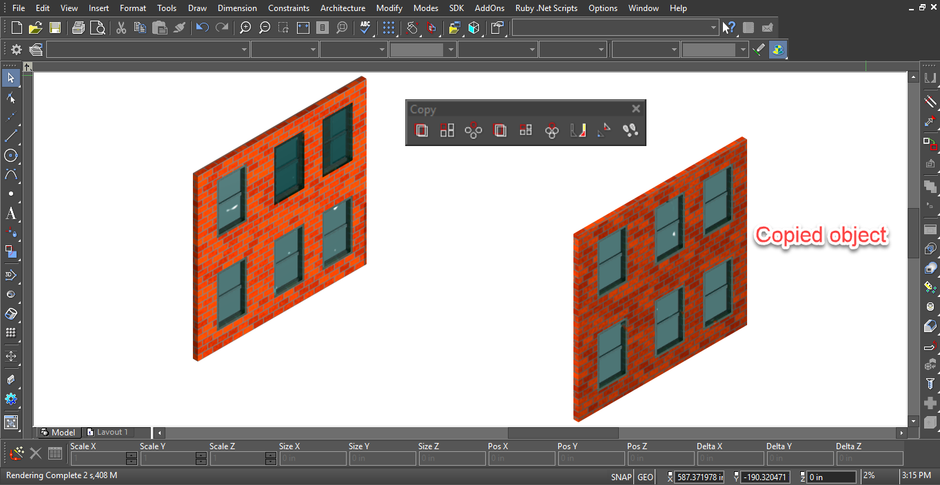
The Copy Entities tools enable you to make single or multiple copies of selected objects, while precisely controlling the placement of the copies. You can display the Copy toolbar by right-clicking in any toolbar area and selecting Copy.
Note: You can also make simple copies of objects in Select Edit . For other tools you can use to copy objects relative to specific points,
The Copy Entities tools can be used on 2D and 3D objects. For the objects you want to use, be sure the Selector is set correctly (2D, 3D, or both).
These tools are typically invoked when objects are already selected. You can also invoke them even if no objects are currently selected, as long as the Select tool is active. In this case, the local menu option Select can be used to select objects to copy. Close the Select option when all objects are selected.
Local menu options:
For all of the Copy tools (except Copy in Place), the following local menu options are available:

Select: Enables you to add or remove objects from the selection set. Once the objects have been selected, deactivate this object to continue with the operation.
Repeat: Enables you to copy the selected objects again. Otherwise, the operation ends once the first operation is complete. Make Pattern Object as Result: Creates a Pattern object as a result of using the Copy tool. In TurboCAD you can use Auto Constraints and to control the spacing of pattern-copied objects.
or Bar and the drawing area. You can press Tab to enter the Inspector Bar, and click once in the drawing or press Esc to return to the drawing.
Array Copy

Default UI Menu: Modify/Array/Array
Ribbon UI Menu:
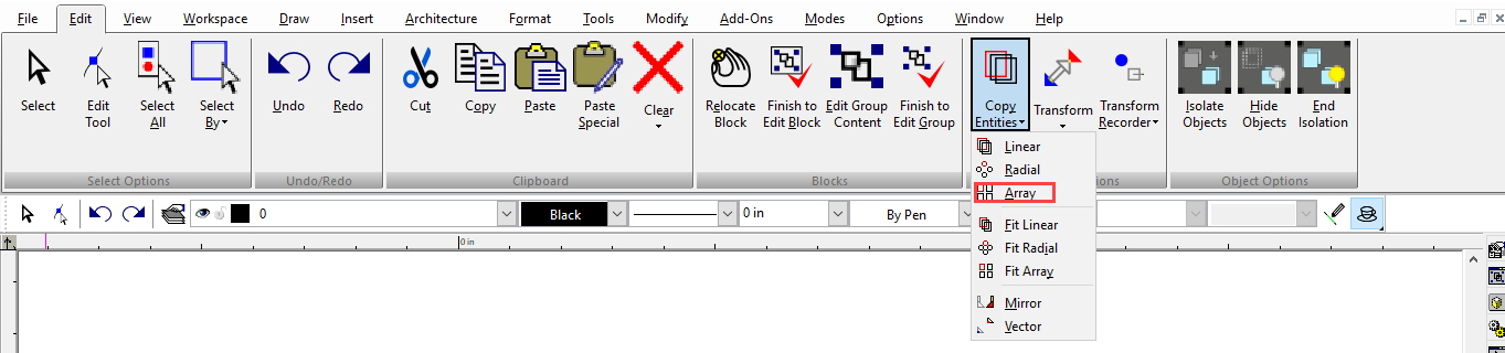
Creates copies of 2D or 3D objects into a 2D or 3D linear array, in which each copy is separated by a specified distance.
-
Select the objects you want to copy and activate Array Copy.
-
In the Inspector Bar, enter the total number of Rows, Column, and Levels (number of copies in Z) that will result.
-
Set the distance between adjacent copies by using the mouse to define the copy vector, or enter Step values in the Inspector Bar. The copy vector is defined from the reference point of the selection set.
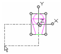
- The copies are made after the vector has been defined.
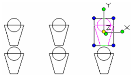
Rows = 2, Columns = 3
- Click anywhere to exit Select mode, or press Esc.
Copy In Place

Default UI Menu: Edit/Copy in Place
Ribbon UI Menu:
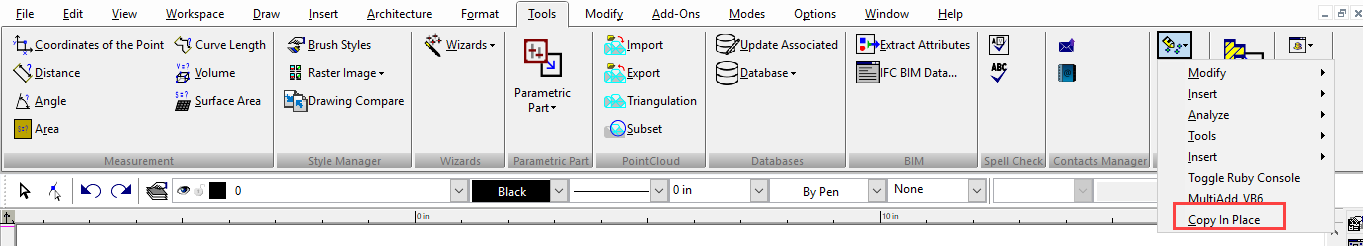
Copy in Place creates a copy of all selected objects in exactly the same place as they are.
- Select the objects you want to copy and select Copy in Place.
- The resulting copied objects will now be the selected objects.
Fit Array Copy

Default UI Menu: Modify/Array/Fit Array
Ribbon UI Menu:
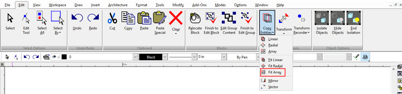
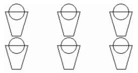
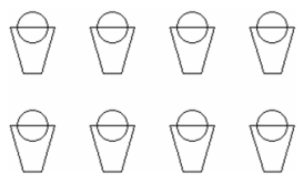
Creates copies of 2D or 3D objects into a 2D or 3D linear array, in which a specified number of copies are evenly spaced.
-
Select the objects you want to copy and activate Fit Array Copy.
-
In the Inspector Bar, enter the total number of rows, columns, and levels (number of copies in Z) that will result.
-
Set the distance between first and last copies in each direction by using the mouse to define the entire copy array boundary, or enter Bound values in the Inspector Bar. The copy array is defined from the reference point of the selection set.
- The copies are made after the array boundary has been defined.
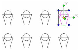
Rows = 2, Columns = 4
- Click anywhere to exit Select mode, or press Esc.
Fit Linear Copy

Default UI Menu: Modify/Array/Fit Linear
Ribbon UI Menu:
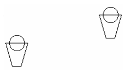
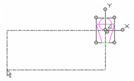
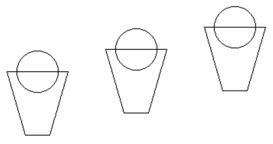
Creates copies of 2D or 3D objects along a straight line, along which a specified number of copies are evenly spaced.
-
Select the objects you want to copy and activate Fit Linear Copy.
-
In the Inspector Bar, enter the number of Sets - the total number of objects that will result.
-
Set the distance between the first and last copies by using the mouse to define the copy vector, or enter size values in the Inspector Bar. The copy vector is defined from the reference point of the selection set.
- The copies are made after the vector has been defined.
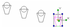
Sets = 4
- Click anywhere to exit Select mode, or press Esc.
Array Fit Linear command take into account the all the properties of the object of which linear array is being created e.g. Workplane, etc. In addition, the processing of ADT objects, i.e. File Open, House Wizard, etc. has been markedly sped up.
Example 2:
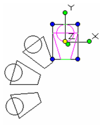
Fit Radial Copy

Default UI Menu: Modify/Array/Fit Radial
Ribbon UI Menu:
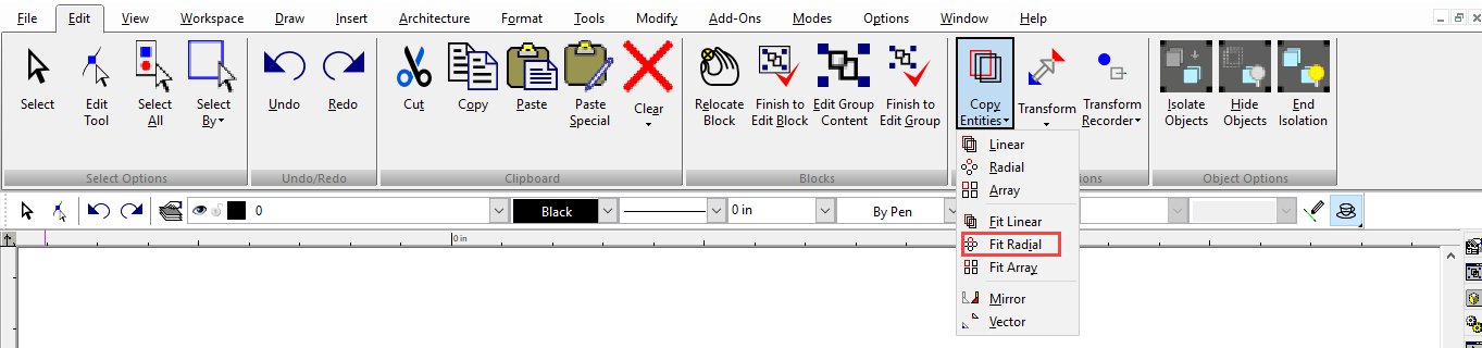
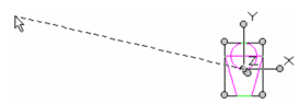
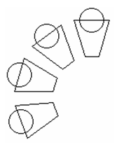
Creates copies of 2D or 3D objects along an arc, along which a specified number of copies are evenly spaced and rotated.
-
Select the objects you want to copy and activate Fit Radial Copy.
-
In the Inspector Bar, enter the number of Sets - the total number of objects that will result.
-
Set the angle the first and last copies by using the mouse to define the center of the copy arc and the angle, or enter the angle in the Inspector Bar. You can enter a rotation value to set the rotation of each copy relative to the previous one. If Rotation = 0, the copies will not rotate at all.
The copy arc is defined from the reference point of the selection set.
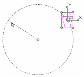
- The copies are made after the arc has been defined.
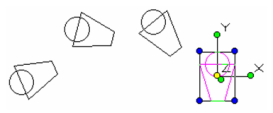
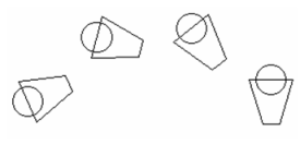
Sets = 4
- Click anywhere to exit Select mode, or press Esc.
Note: For copying in 3D, the copy arc is positioned on the current workplane. Each copy is rotated around the axis perpendicular to the workplane, passing through the reference point of the selected objects.
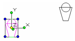
Mirror Copy
Default UI Menu: Modify/Copy/Mirror
Ribbon UI Menu:
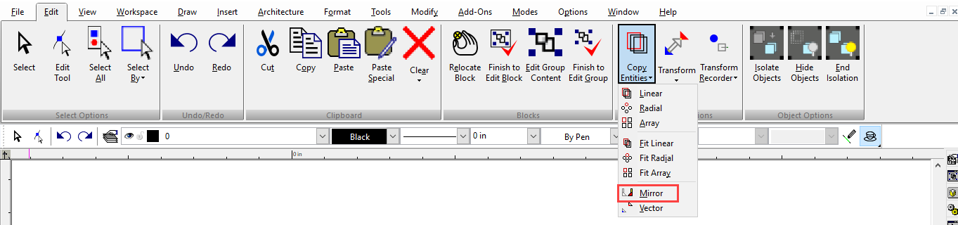
Options: Mirror along line: Creates a mirror image of an object by defining a mirror line. Mirror along face: Select a face plane along which Mirror operation should be performed. Try to create single object: When selected TurboCAD will attempt to add original object and its mirrored copy Create a mirror image of an object by defining a mirror line:
-
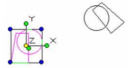
Select the objects you want to mirror and activate Mirror Copy.
-
Define the mirror line by selecting two points, or by selecting one point and entering an angle in the Inspector Bar.
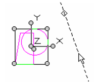
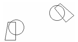
- The mirror copy is made after the mirror line has been defined.
- Click anywhere to exit Select mode, or press Esc.
Create a mirror image of an object by selecting a face:
- Select the objects you want to mirror and activate Mirror Copy.
- Define the mirror line by a face.
- The mirror copy is made after the mirror line has been defined.Click anywhere to exit Select mode, or press Esc.
Note: For text to be mirrored, it must be Flexible. Otherwise the text will read the same way on both sides of the mirror line. When selecting objects for mirroring, especilly text or dimensions, it is important that the selector be in 2D Mode. If the selector is in 3D mode the text will be mirrored as well as any geometry. In 2D mode the text remains normal (in readable orientation) while the geometry is mirrored.
Linear Copy
Default UI Menu: Modify/Array/Linear
Ribbon UI Menu:
Creates copies of 2D or 3D objects along a straight line, in which each copy is separated by a specified distance.
-
Select the objects you want to copy and activate Linear Copy.
-
In the Inspector Bar, enter the number of Sets - the total number of objects that will result.
-
Set the distance between adjacent copies by using the mouse to define the copy vector, or enter Step values in the Inspector Bar. The copy vector is defined from the reference point of the selection set.
Note: To make a single copy using a distance vector that does not start at the reference point of the selected objects
- The copies are made after the vector has been defined.
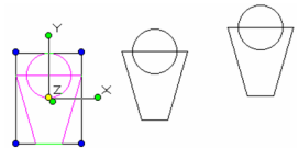
Sets = 3
- Click anywhere to exit Select mode, or press Esc.
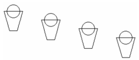
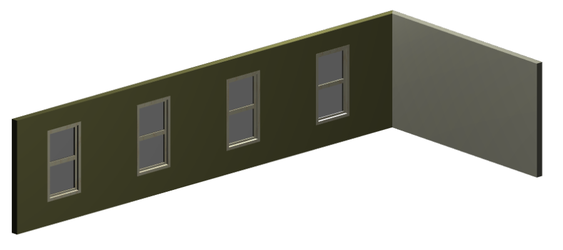
A good use for Fit linear copy is for architectural smart object like windows.
With new improvement in TC 2019, Array Fit Linear command take into account the all the properties of the object of which linear array is being created e.g. Workplane, etc.
Fit Radial Copy
Default UI Menu: Modify/Array/Fit Radial
Ribbon UI Menu:
Creates copies of 2D or 3D objects along an arc, along which a specified number of copies are evenly spaced and rotated.
-
Select the objects you want to copy and activate Fit Radial Copy.
-
In the Inspector Bar, enter the number of Sets - the total number of objects that will result.
-
Set the angle the first and last copies by using the mouse to define the center of the copy arc and the angle, or enter the angle in the Inspector Bar. You can enter a rotation value to set the rotation of each copy relative to the previous one. If Rotation = 0, the copies will not rotate at all.
The copy arc is defined from the reference point of the selection set.
- The copies are made after the arc has been defined.
Sets = 4
- Click anywhere to exit Select mode, or press Esc.
Note: For copying in 3D, the copy arc is positioned on the current workplane. Each copy is rotated around the axis perpendicular to the workplane, passing through the reference point of the selected objects.
Mirror Copy
Default UI Menu: Modify/Copy/Mirror
Ribbon UI Menu:
Options: Mirror along line: Creates a mirror image of an object by defining a mirror line. Mirror along face: Select a face plane along which Mirror operation should be performed. Try to create single object: When selected TurboCAD will attempt to add original object and its mirrored copy Create a mirror image of an object by defining a mirror line:
-
Select the objects you want to mirror and activate Mirror Copy.
-
Define the mirror line by selecting two points, or by selecting one point and entering an angle in the Inspector Bar.
- The mirror copy is made after the mirror line has been defined.
- Click anywhere to exit Select mode, or press Esc.
Create a mirror image of an object by selecting a face:
- Select the objects you want to mirror and activate Mirror Copy.
- Define the mirror line by a face.
- The mirror copy is made after the mirror line has been defined.Click anywhere to exit Select mode, or press Esc.
Note: For text to be mirrored, it must be Flexible. Otherwise the text will read the same way on both sides of the mirror line. When selecting objects for mirroring, especilly text or dimensions, it is important that the selector be in 2D Mode. If the selector is in 3D mode the text will be mirrored as well as any geometry. In 2D mode the text remains normal (in readable orientation) while the geometry is mirrored.
Linear Copy
Default UI Menu: Modify/Array/Linear
Ribbon UI Menu:
Creates copies of 2D or 3D objects along a straight line, in which each copy is separated by a specified distance.
-
Select the objects you want to copy and activate Linear Copy.
-
In the Inspector Bar, enter the number of Sets - the total number of objects that will result.
-
Set the distance between adjacent copies by using the mouse to define the copy vector, or enter Step values in the Inspector Bar. The copy vector is defined from the reference point of the selection set.
Note: To make a single copy using a distance vector that does not start at the reference point of the selected objects,
- The copies are made after the vector has been defined.
Sets = 3
- Click anywhere to exit Select mode, or press Esc.
A good use for linear copy is for architectural smart object like windows. This feature became available in the TurboCAD 2017.
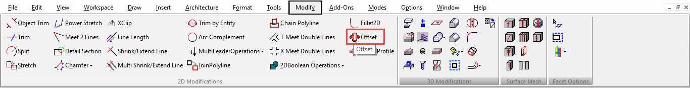
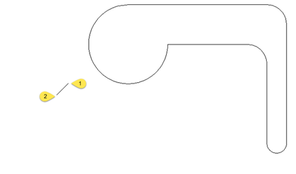
Offset
Default UI Menu: Modify/Offset/Offset
Ribbon UI Menu:
Creates one or more offset copies of a 2D object. The object can be open or closed. For closed objects, the offsets will also be closed (in most cases). You can offset these objects:
- Lines
- Arcs
- Circles
- Ellipses and elliptical arcs; creates a spline
- 2D Polylines
- 3D Polylines whose points remain on one plane; creates a 2D polyline.
- 2D Curves; Bezier and Spline
- 3D Curves whose points remain on one plane; creates a 2D spline.
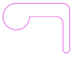
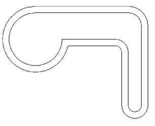
The offsets are created so that linear segments remain parallel. When possible, arc start and end angles remain the same as well. Various options become available depending if the Skip Define Distance step option is on. This is normally active by default.
A Multiple option may be used after selecting the source object instead of specifying a Sets amount.
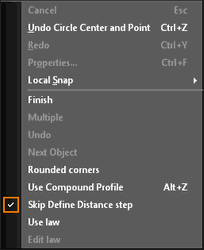
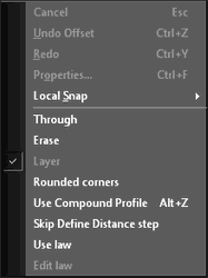
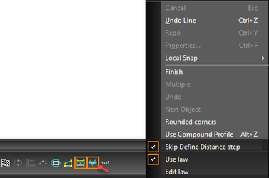
Skip Define Distance step:
active inactive.
- Select the Offset tool.
- Set the offset Distance either by entering a value in the Inspector Bar or by selecting two points. The angle of this line does not matter; the value of its length will be used.
- Enter the number of Sets in the Inspector Bar. This is the total number of copies, plus the original.

- Select the object.
- Select the side of the object where you want to place the copies.
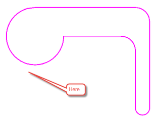
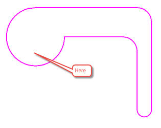
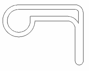
The offset copies are made on the selected side. In this case, the left object was offset to outside and the right object to the inside. Where lines overlap, they are automatically trimmed.
6. If you enter a plus or minus Z Offset value, each offset copy will be separated from the adjacent one by this height; thus, on a new workplane.

7. You can use the same parameters to offset other objects, you can change the parameters, or select Finish from the Local Menu or Inspector Bar to exit the tool.
Options:
Finish: Closes the Offset tool and returns you to the Line tool. Multiple: When an object is intially selected, the Multiple option becomes selectable. If selected, every click of the mouse (LMB) will offset a single copy from the last copy. If more than 2 sets are specified, only one copy is made. Undo: Undoes the offset in a "Multiple" operation. Next Object: Exits the current selected object in a "Multiple" operation and allows you to choose another object. Rounded Corners:The exterior corners (relative to the offset direction) will be rounded. Use Compound Profile: When active, all the objects whose endpoints meet, are selected as if they were a single polyline. Skip Define Distance step: When active (default), the Offset tool uses the last Distance value.When inactive, three choices become available and a Distance value needs to be specified in the Inspector Bar or by selecting two points. Use Law: Uses a law (formula) to modify and deform the offset copies. Edit Law: Edit and select the laws to be used The following options are only available when the Skip Define Distance step option is turned off: Through: Offset an object through a point that you click/snap to. Erase: The origin object is deleted and just the offset remains. Layer: Specify a Layer. If the Layer option is turned off the following two options appear: Current: The current active drawing layer. Source: Uses the layer of the source object.
Offset with Law
Laws are mathematical functions in the form of a formula. They are used to define how resulting objects are modified. They are composed and selected in the Laws Editor which is specific to each tool that uses laws and can be opened from that tool.
To open Laws Editor:
-
Select Offset tool from Modify menu.
-
Select Use law from local menu or inspector bar.
- Now select Edit law.
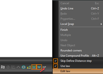
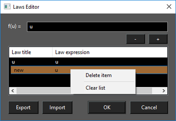
Laws Editor will open.
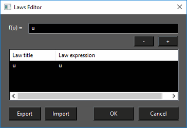
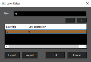
To use a law:
- Open the Laws Editor.
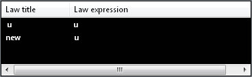
- Select the desired law in the Laws table by double-clicking and press OK. The law that is applied is what is in the formula field.
To create a law:
- Type the desired formula into the formula field.
- Press the + (plus) button.
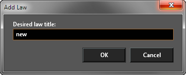
- Type in a titke for the law and press OK. The new law will appear in the Laws table
To Delete a law:
- Open the Laws Editor.
- Click on the Law in the Laws table to select it.
- Right click and select Delete, or press the - (minus) button.
Laws cannot be edited but double click a law will load it into the Formula field where it can be altered and then a new altered law added.
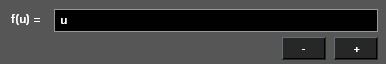
f(u)
In the Offset tool the function are defined as a function of U. Where U is the distance along the object being offset. Therfore the function is dependant upon the direction that the object is drawn. You can determine the direction by looking at the vertex values in the Selection Info palette. The effect of the formula is added to the Offset Distance.
Examples:
All of these examples are set with the Offset Distance set to Zero (0).
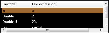
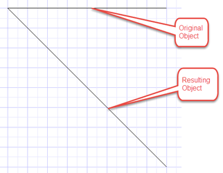
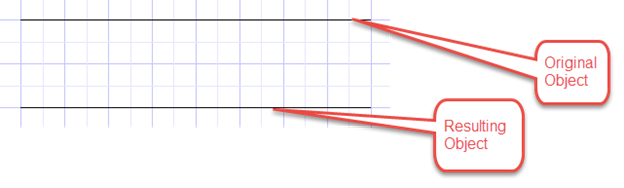
Setting f(u) = u
 Setting f(u) = 2
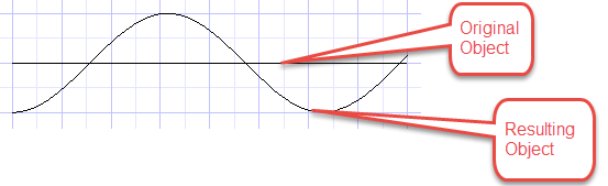
 Setting f(u) = cos(u)
 Setting f(u) = u
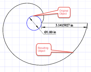 Notice that the distance between the start and end of the resulting spiral is ~Pi since the diameter of the original circle is 1.0.
Import and Export laws:
The laws created can also be saved by using the export button in the laws editor. After creating a law, press export and enter the name you want give to the file then press save.
You can also import laws. Open laws editor, and select import then choose the desired file and press open. The laws will be loaded from file and displayed in the laws editor.
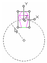
Radial Copy

Default UI Menu: Modify/Array/Radial
Ribbon UI Menu:
Creates copies of 2D or 3D objects along an arc, in which each copy is separated by a specified angle and rotation (optional).
-
Select the objects you want to copy and activate Radial Copy.
-
In the Inspector Bar, enter the number of Sets - the total number of objects that will result.
-
Set the angle between adjacent copies by using the mouse to define the center of the copy arc and the angle, or enter the angle in the Inspector Bar. You can enter a rotation value to set the rotation of each copy relative to the previous one. If Rotation = 0, the copies will not rotate at all. By default, Rotation = Angle.
The copy arc is defined from the reference point of the selection set.
- The copies are made after the arc has been defined.
Sets = 4
- Click anywhere to exit Select mode, or press Esc.
Note: For copying in 3D, the copy arc is positioned on the current workplane. Each copy is rotated around the axis perpendicular to the workplane, passing through the reference point of the selected objects.
Vector Copy

Default UI Menu: Modify/Copy/Vector
Ribbon UI Menu:
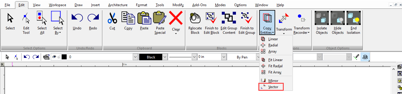
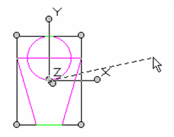
Creates a single copy of an object at a specified angle and distance from the reference point of the original.
-
Select the objects you want to copy and activate Vector Copy.
-
Define the copy vector by selecting two points, or by selecting one point and entering the length and angle in the Inspector Bar. The copy vector can be anywhere, but it is applied to the reference point of the selection set.
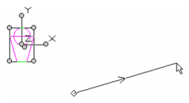
Note: To make one or more copies using a distance vector that starts at the reference point of the selected objects,
- The copy is made after the vector has been defined.
- Click anywhere to exit Select mode, or press Esc.