Hatching
(Available in all TurboCAD Variants)
Default UI Menu: Draw/Hatches
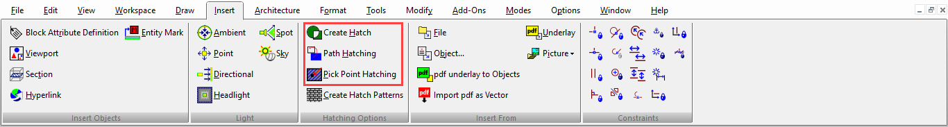
Ribbon UI Menu:
You can display the Hatch toolbar by right-clicking in any toolbar area and selecting Hatch.
 You can also fill a closed object by adjusting the Brush settings in the object's Properties window. Another way is to use the Colors and Brushes palette;
Note: If no pattern is specified when an object is selected for hatching, the fill will be solid.
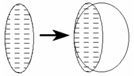
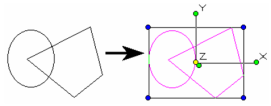
Associative Hatching
Associative hatches are linked to their boundaries, and update when their boundaries are modified.
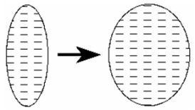
Non-associative hatches are independent of their boundaries.
To set hatching to be associative, check Associative Hatch on the Display page of the Drawing Setup (Options/Display). To break the link between an associative hatch and its boundary, select both the boundary and the hatch, and select Drop Link from the Inspector Bar or local menu.

Editing a Hatch Pattern
You can change a hatch pattern by selecting an object and changing the pattern listed on the Brush page of its Properties window. If you want to edit a hatch pattern, you will first have to explode it. For associative hatches, you must first explode the object into its boundary and hatch components.
Hatch

Default UI Menu: Draw/Hatches/Create Hatch
Ribbon UI Menu:
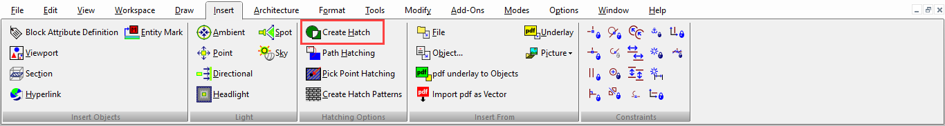
Applies a hatch pattern to a selected closed area. The closed objects must be selected before the Hatch tool can be used.
- Set the hatch pattern by opening the Properties window of the Hatch tool. On the Brush page, select the pattern and other hatch parameters.
2. Use the Select tool to select the objects you want to hatch.
3. Click Hatch or select Format / Create Hatch.
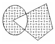
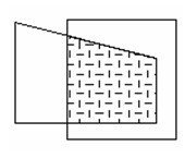
The hatch is not applied to overlapping areas.
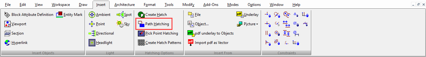
Path Hatching

Default UI Menu: Draw/Hatches/Path Hatching
Ribbon UI Menu:
Applies a hatch pattern to a closed boundary of segments, defined manually.
-
Set the hatch pattern by opening the Properties window of the Hatch tool. On the Brush page, select the pattern and other hatch parameters.
-
Activate Path Hatching.
-
Select points to define segments of the boundary. The points do not have to lie on existing objects; they can be anywhere. A magenta line indicates the progress of the boundary.
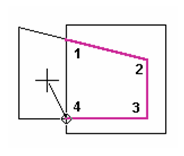
- Select the first point again to close the boundary, or select Close from the local menu or Inspector Bar.
Local menu option: By Entity: Use this option to select the entire perimeter of an object. If you have already selected boundary points, By Entity will select the perimeter up to the next point. This is especially useful when you are trying to hatch curved objects.
Pick Point and Hatch
 This command has to be activated via the Customize dialog. Applies a hatch pattern to a closed boundary, by clicking one point within the desired boundary. This tool recognizes overlaps and islands.
1. Set the hatch pattern by opening the Properties window of the Hatch tool. On the Brush page, select the pattern and other hatch parameters.
2. Activate Pick Point and Hatch.
3. Click any point within the desired boundary to create the hatch.
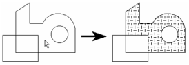
4. To hatch another area, you must activate the tool again and pick another point.
Pick Point Hatching
TurboCAD 2019 (All versions)
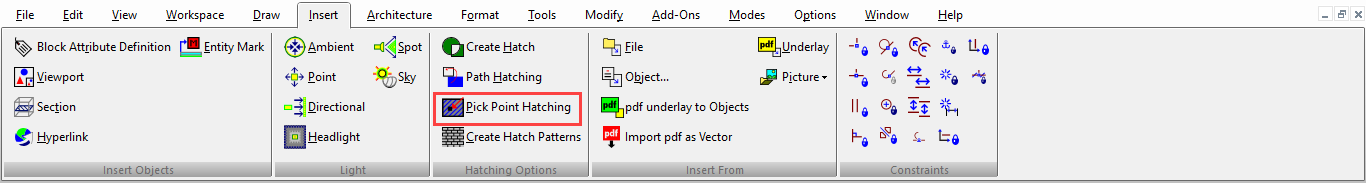
Default UI Menu: Draw/Hatches/Pick Point Hatching
Ribbon UI Menu:
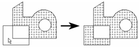
Pick Point Hatching is an enhanced version of Pick Point and Hatch.
 Applies a hatch pattern to a closed boundary, by clicking one point within the desired boundary. This tool recognizes overlaps and islands.
- With Pick Point Hatching you can pre-set the hatch's pattern Line Color, Line Pattern, Line Width, Brush Color and Brush Pattern from the Properties toolbar directly above the drawing area.
- Activate Pick Point Hatching
- Click any point within the desired boundary to create the hatch.
- You can hatch additional areas by clicking until you cancel out of the tool.
Pick point hatching is now working in internal areas. Pick point Hatch now also works when there are gaps between boundary areas.
New “Gaps” field is added in the Inspector Bar.
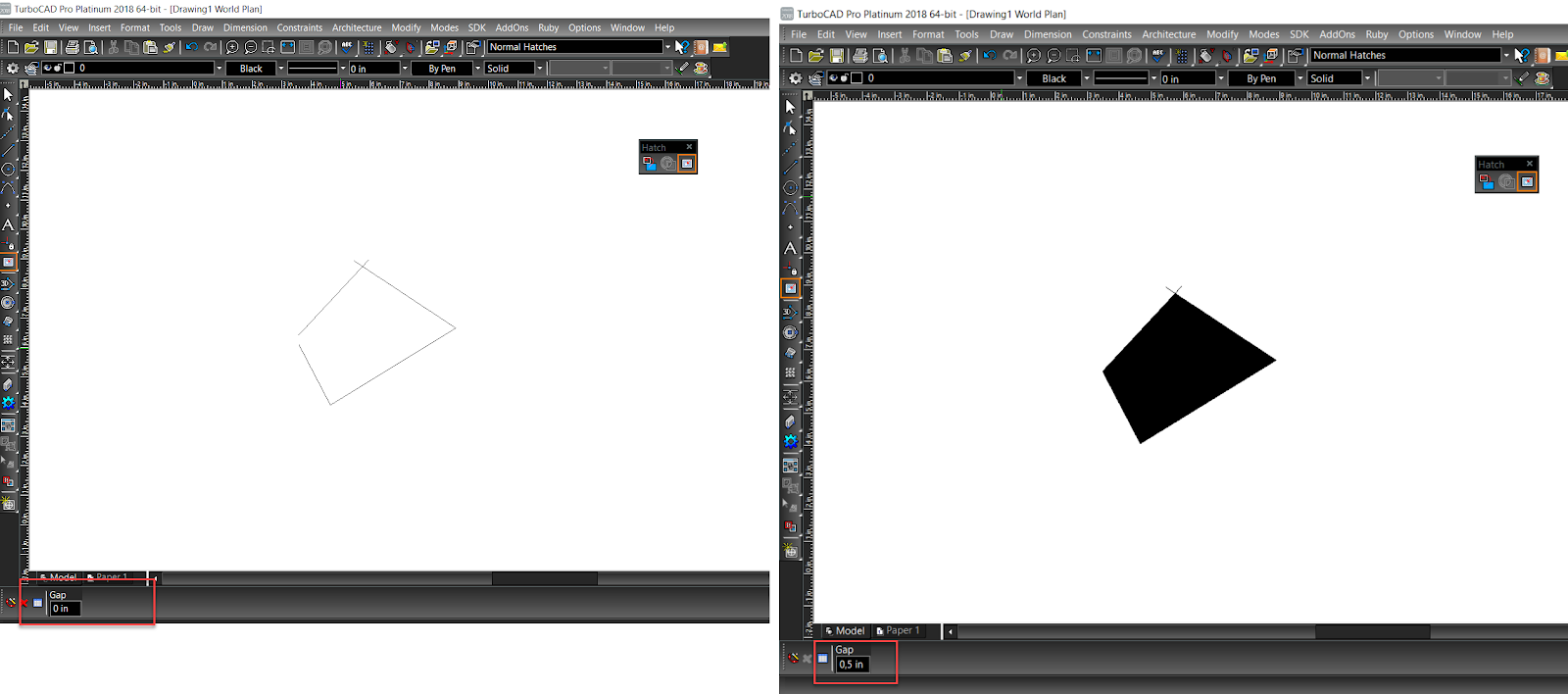
-
This will work with gaps in 2D objects.(For example,trying to fill an area bounded by a Polyline, when there are gaps in the Polyline)
-
It will also apply to ADT objects (Walls, Doors and Windows), allowing to similarly fill in gaps between these objects.