Formatting Objects
This section covers tools for setting the appearance and format of drawing objects and other objects.
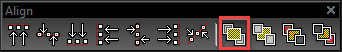
Aligning Objects
(Available in all TurboCAD Variants)
Default UI Menu: Modify/2D Align
Ribbon UI Menu:
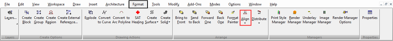
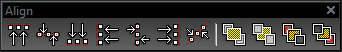
Aligns all currently selected objects, relative to the bounding box of the selection. You can display the Align toolbar by right-clicking in any toolbar area and selecting Align.
- Select the objects you want to align.
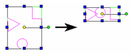
- From the Align menu (or the Align toolbar), select the type of alignment.
For example, Top moves the objects to the top of the bounding box.

Align Along Line
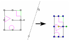
Align objects along a line.
- Select the objects you want to align.
- Select Align line, or click the icon in the Align toolbar.

3. Define the location of the alignment line by selecting one point, then select a second point to set the angle. You can also enter the angle in the Inspector Bar.
Distributing Objects
(Available in all TurboCAD Variants)
Default UI Menu: Modify/2D Distribute
Ribbon UI Menu:
Distributes all currently selected objects, relative to a specified location on the objects (top, left, center, etc.). There must be at least three objects selected for this function to be available.
Objects are distributed between the two most extreme objects, i.e. the farthest left and the farthest right, or highest and lowest. Object order is maintained (top to bottom or left to right).
You can display the Distribute toolbar by right-clicking in any toolbar area and selecting Distribute.
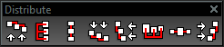
- Select the objects you want to distribute.
- From the Distribute menu (or the Distribute toolbar), select the type of distribution.
For example, Top arranges the objects so that the tops of their bounding boxes are evenly spaced vertically.

 Bottom arranges the objects so that the bottoms of their bounding boxes are evenly spaced vertically.
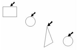
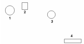
For vertical distribution, Middle means equal spacing between reference points, and Space means equal spacing between object bounding boxes. For horizontal distribution, Center means equal spacing between reference points, and Distance means equal spacing between object bounding boxes. In this example, Object 2 is the highest, followed by 1, 3, and 4.
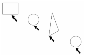
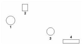
After vertical distribution, the highest and lowest objects (Objects 2 and 4) remain in place. Objects 1 and 3 are moved so that top-to-bottom order remains the same: 2, 1, 3, 4.
Exploding Objects
(Available in all TurboCAD Variants)
Hotkey: Alt+Shift+E
Default UI Menu: Modify/Explode
Ribbon UI Menu:
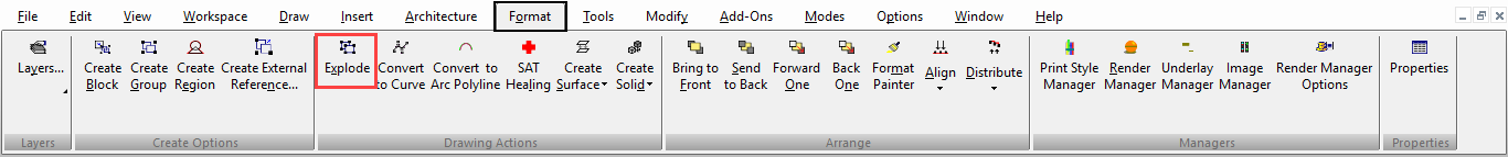
Breaks an object, group, or block into its constituent parts. Each explosion is one level deep, to preserve the hierarchical structure of objects. Objects must be selected first in order to be exploded.

Note: The opposite of Explode is to join objects into a group (Format / Create Group).You can also use Explode to split solids that are difficult to split using 3D editing tools. Different types of objects are exploded differently, and use different explosion levels. Blocks and groups are first broken into their individual objects, then each object can then in turn be exploded. Polylines are broken into individual segments. Dimensions are exploded into lines, arrows, and text, then each of these can also be exploded. Double-line objects are exploded into single lines. You can explode a solid object twice to turn it into an exploded (node-editable) surface object.
When using Explode, it can be helpful to open the Selection Info Palette , so that you can see the start condition and end results.
Exploding Example - Polyline
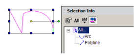
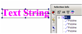
- Create a multi-segmented polyline (with Auto Add Constraints off) and select it. In the Selection Info Palette, the object type is indicated as "Polyline."
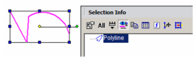
- Select Explode, or click the Explode icon. The polyline is exploded into one arc and one small polyline.
-
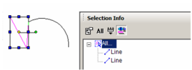
Select the small polyline.
-
Explode it into its constituent parts - two lines.
Exploding Example - Text
- Use the Text tool to create a text object, and select it.
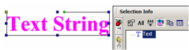
- Select Explode, or click the Explode icon. The text is exploded into a Group of Graphics.
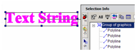
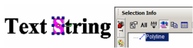
- Explode again, and now the group consists of one polyline representing each character.
- Select any character; it is identified as a polyline.
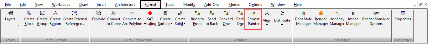
Format Painter
(Available in Platinum, Professional and Deluxe)
Hotkey: Ctrl+Shift+P
Default UI Menu: Format/Format Painter
Ribbon UI Menu:
Takes properties from one object and applies ("paints") them onto other objects. You can paint all properties or only selected ones.
- Select the source object - the object with the properties you want to apply to other objects.
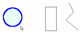
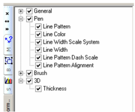
- The Format Painter Palette appears in the palette area, listing all the properties that can be painted.
The list of properties depends on the selected object. For instance, a text object will have a category for Text properties; a sphere will have a category for Sphere properties.
-
By default, all properties are selected. If you want to remove any properties, uncheck the relevant box.
-
Select the object to which you want to paint the properties.
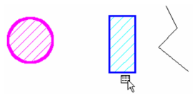
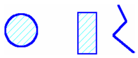
- Select additional objects, if needed. Only the relevant properties will be applied. For example, the circle's Brush properties are not applied to the polyline (open objects cannot be filled).
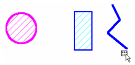
- Select Cancel from the local menu or Inspector Bar.
Local menu options: Make property values preset: If this is selected the Make Property Value Presets dialog will appear. You can specify a name and type of preset that you want to create. The parameters of the preset will be generated from the object you selected, and the properties you specified in the Format Painter palette. Use Palette: Displays or hides the Format Painter Palette.
Mark All: Selects all properties for painting. If the Format Painter Palette is not displayed, the properties will appear in a separate window.
Unmark All: Clears all properties for painting. If the Format Painter Palette is not displayed, the properties will appear in a separate window.
Regions
(Available in Platinum)
Default UI Menu: Modify/Create Region
Ribbon UI Menu:
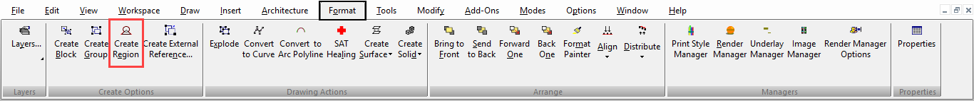
Combines 2D closed objects to form one object, called a region. Any overlap between selected objects is removed. The results are identical to using 2D Add, except that this tool requires that the objects be selected first. When using 2D Add, you select the objects during the operation.
Stacking Objects
(Available in all TurboCAD Variants)
Default UI Menu: Tools/Draw Order
Ribbon UI Menu:
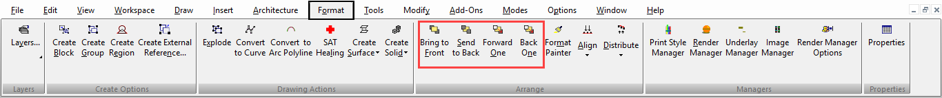
Objects are "stacked" when created - each object is created "on top" of the previous object. This sometimes has no visual effect, but stacking order can matter in the case of images and filled or hatched objects.
Note: Stacking is not related to layers, and changing an object's layer does not effect its position in the object stack.
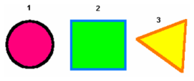
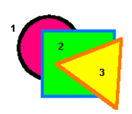
This example contains three filled objects that were created in the indicated order:
Tip: You can press F6 to select the first object you created. Keep pressing F6 to scroll through the objects in their creation order. Press F7 to select the last object created, and repeat F7 to scroll backwards.
If you move the objects so that they overlap, you can see that the first object is at the bottom of the stack; the last object is at the top.
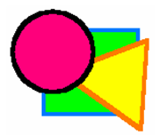
- Select the circle and select Bring to Front.
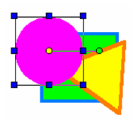
- The circle is now at the top. This, in effect, changes the creation order - the circle is now considered the most recent object. (You can verify this by pressing F7.)
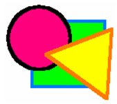
- Select the circle again and select Back One. Rather than sending the circle to the bottom of the stack, it moves just one level down.
If you change the stacking order of multiple selected objects, the selection set will move as a whole. The relative stacking order of objects within the selection set is maintained.