Bending and Unbending
(Available only in Platinum)
Default UI Menu: Modify/Modify 3D Objects/Bending
Ribbon UI Menu:
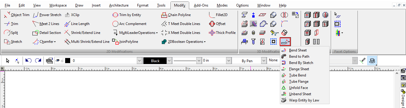
These tools are used for bending existing sheets and tubes (pipes) or for adding flanges on sheets and tubes. There are also tools for unbending.
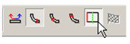
These tools are available on theModify toolbar, which you can display by right-clicking in any toolbar area and selecting 3D Modify.

Bend Sheet
Default UI Menu: Modify/Modify 3D Objects/Bending/Bend Sheet
Ribbon UI Menu:
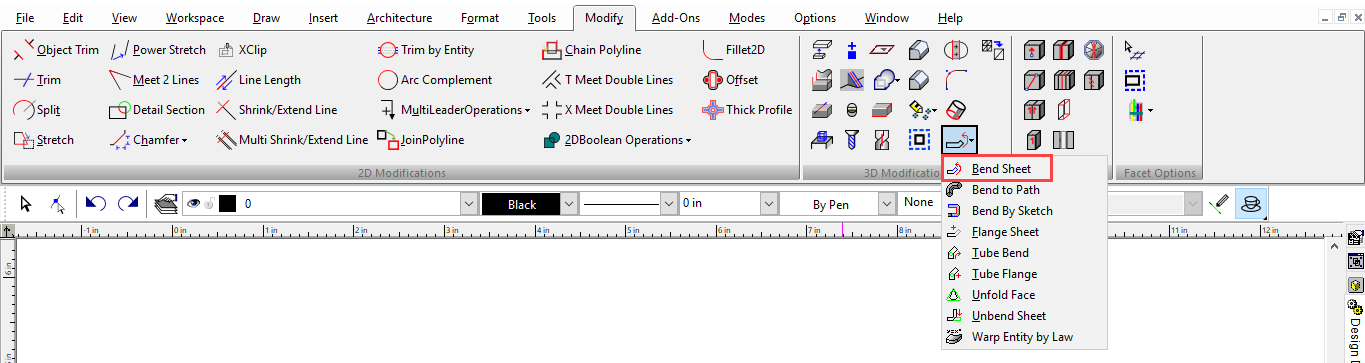
Bends a solid ACIS object, most commonly a sheet with thickness (Box).
Note: You can unbend the object using Unbend Sheet.
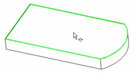
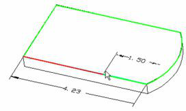
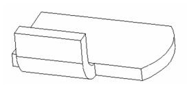
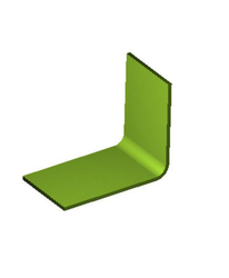
- Start with a shallow Box or a Simple Extrude based on a polyline or rectangle. Add a line to the top.
- Activate Bend. Select the face you want to bend.
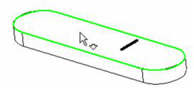
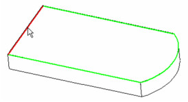
- Then select the line about which you want to bend the solid. The line must lie on the solid face you selected.
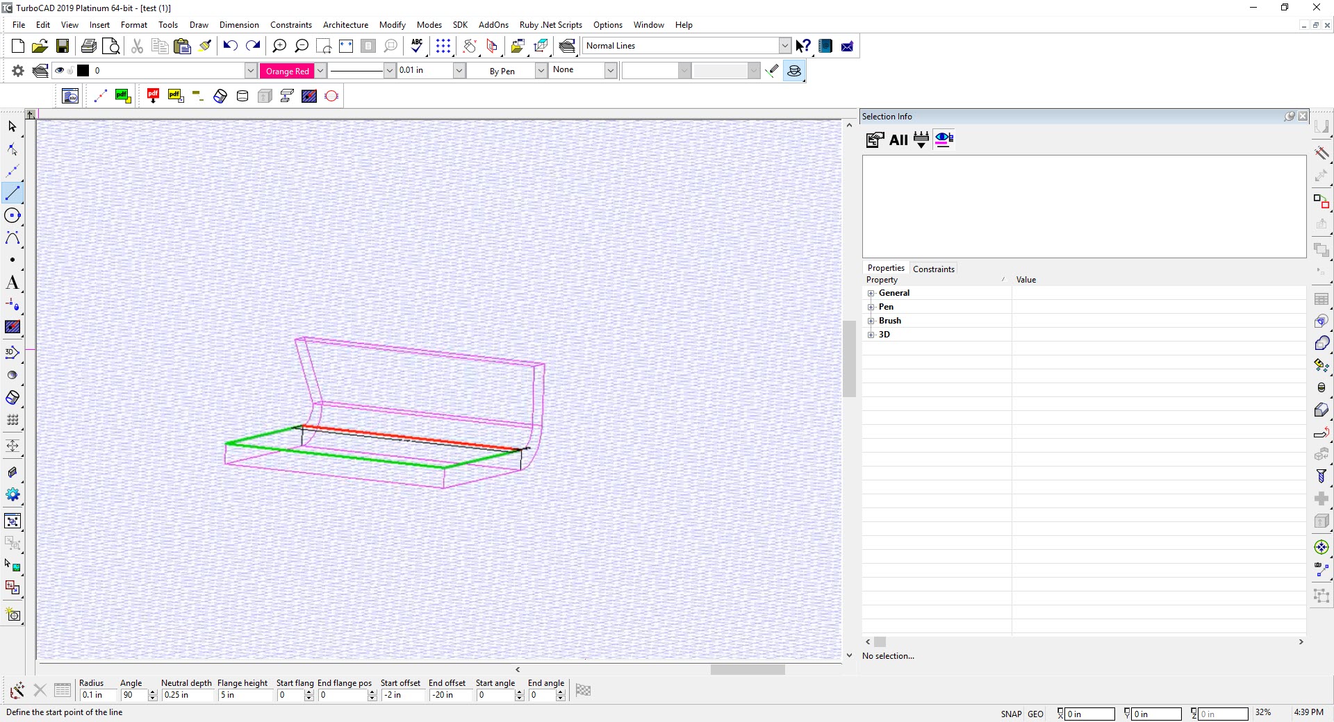
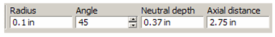
- Set the bending Radius and Angle. The default method is Start, in which the bend starts where the top face meets the selected line.
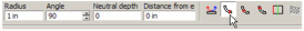
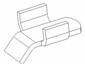
The preview shows how the final result will look.
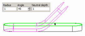
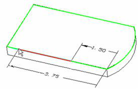
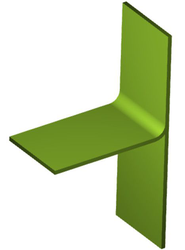
- Switch to Center. In this case, the center of the bent solid meets the selected line (or its projection into the solid).
- Switch to End. In this case, the bottom face of the bent solid meets the selected line (or its projection).
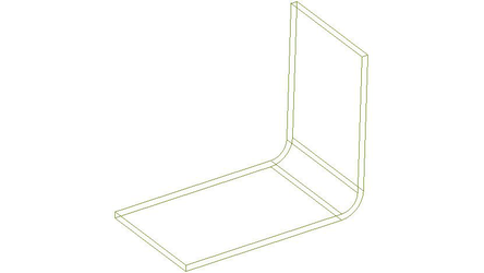
- Select Left Side. The bend now starts from the other end of the solid.
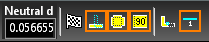
- The Neutral Depth is the distance into the depth of material, along which there will be no tension or compression.
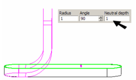
- The Angle is measured from the plane of the bending face.
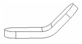
- When the parameters are set, select Finish from the local menu or Inspector Bar to complete the bend.
By Distance from Edge
This option of the Bend tool enables you to define where the bend starts from a linear edge of the planar face.
- Start with a solid that has at least one linear edge. The first step is to select the face that will bend.
- Then select the linear edge from which the bend distance will be defined.
- Pull the cursor from this edge to set the bend distance. Once you click to set the distance, you can change it by clicking again. You can also set the distance in the Inspector Bar.
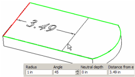
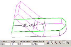
- The preview shows how the final result will look.
Bend to Path
(Available only in Platinum)
Default UI Menu: Modify/Modify 3D Objects/Bending/Bend to Path
Ribbon UI Menu:
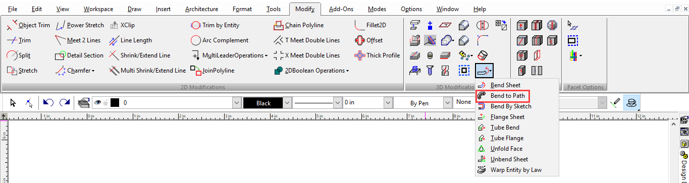
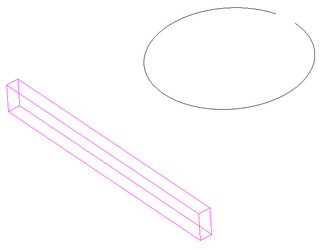
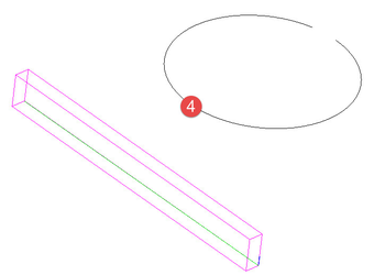
This tool bends a ACIS solid to conform to a 2D path created from a polyline, arc, or curve. The 2D entity must not be closed. To use the Bend to Path tool:
- Select the Bend to Path tool.
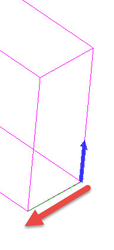
- Select the solid to be bent.
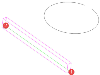
- Specify the Inside/Outside axis by selecting a first point and then a second point. This axis defines the line along the object that will be bent around the path.
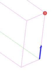
- Specify the initial direction of bending by selecting a point or by entering an angle value into the Inspector bar. The direction is indicated by a blue arrow. This point and the initial point of the inside/outside axis combine to create a bend axis which defines the orientation of the object as it is bent around the path. After creation this value can be changed via the Propeties in the selection info palette if the Part Tree is turned on (Highly Recommended).
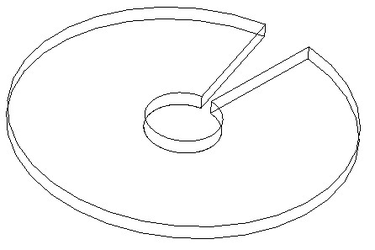
- Select the path to that the object will be bent around.
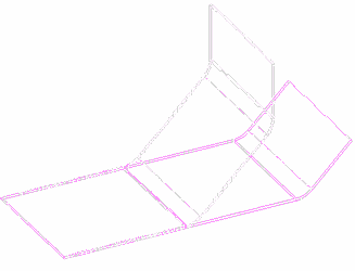
The result:
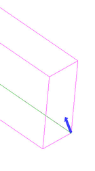
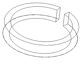 If the inside/outside axis had been diagonal...
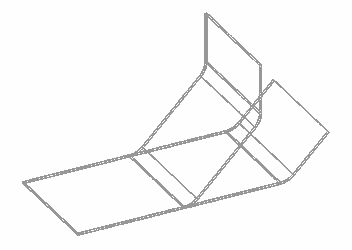
 This would have been the result:
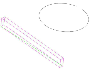
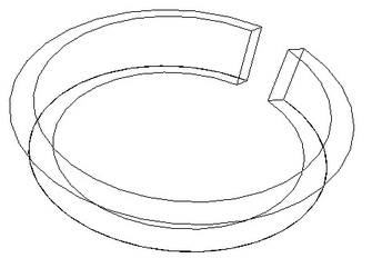
 If the inside/outside axis had be drawn along the base...
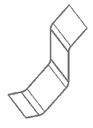
 This would have been the result:
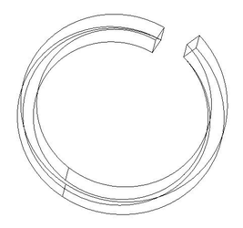
 If the bend axis had been defined diagonally...
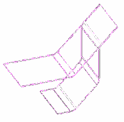
 This would have been the result:
 Options:
- Leave source copy: When this option is selected a copy of the original object will be left in the model. It can be toggled via the Local menu or the Inspector bar.
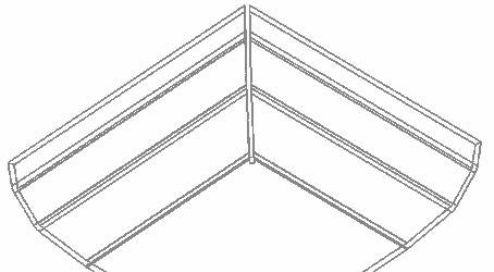
Bend by Sketch
(Available only in Platinum)
Default UI Menu: Modify/Modify 3D Objects/Bending/Bend by Sketch
Ribbon UI Menu:
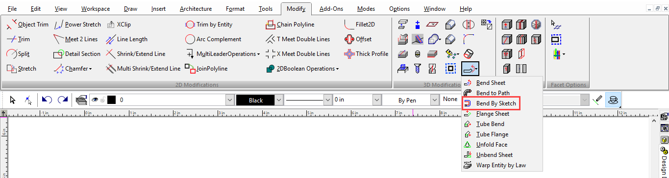
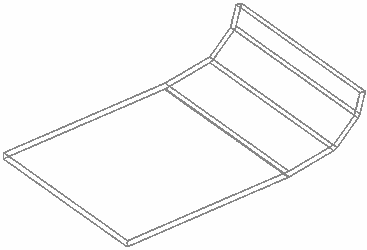
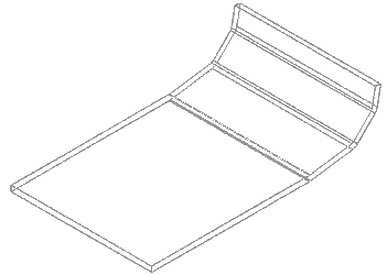
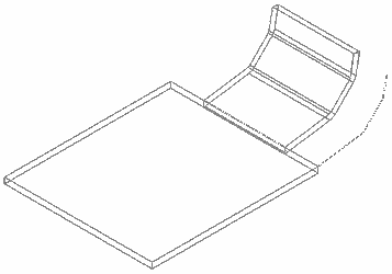
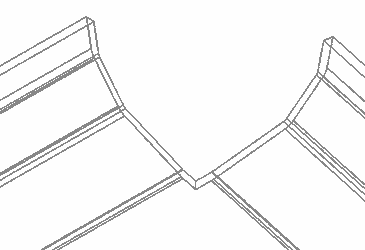
Extends and bends a sheet body (a flat object) along a selected sketch defined by a polyline.
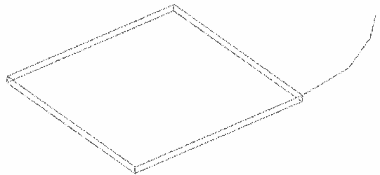
 Note: The polyline must begin on the initial edge of the sheet body. In addition the sketch must be on the plane which is perpendicular to the initial edge. Finally, the polyline must be comprised of only line segments.
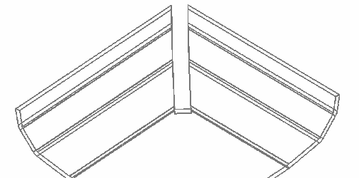
To Bend by Sketch
Note: The polyline must begin on the initial edge of the sheet body. In addition the sketch must be on the plane which is perpendicular to the initial edge. Finally, the polyline must be comprised of only line segments.
To Bend by Sketch
- Select the tool.
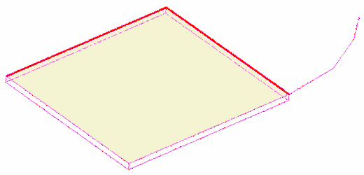
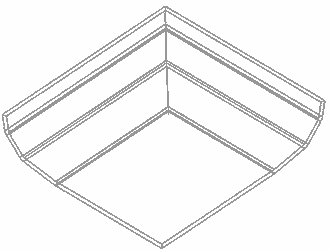
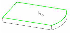
- Select the sheet body.
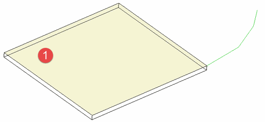
- Select the Sketch.
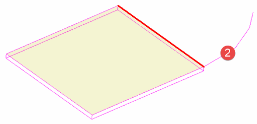
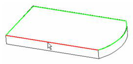
- Hold down the SHIFT key and click on the additional edges which should be included.
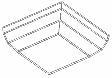
- Specify the values for the tool options.
- Click Finish.
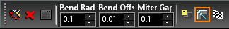
Options
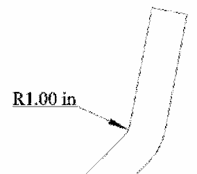
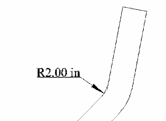
Bend Radius: Set the internal bend radius at each vertex.
 Bend Offset: Sets the value for how far the edges of the bend will be offset from the end of the initial edges. This value is ignored when mitering is in use.
 Miter Gap Width: Set the width of the gap between mitered sections when mitering is used.
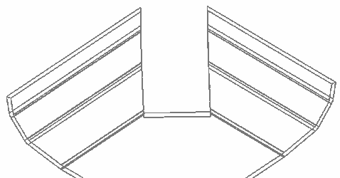 Cut Corners: Clips the corner back to the offset.
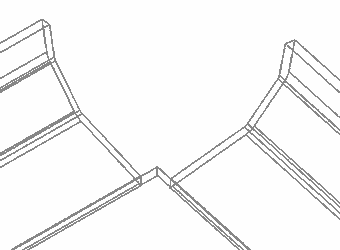
 Auto Miter: Causes adjacent bending to meet at a miter
Flange
Default UI Menu: Modify/Modify 3D Objects/Bending/Flange Sheet
Ribbon UI Menu:
Adds a bend onto the edge of a solid (ACIS) object, most commonly a sheet with thickness (Box).
Note: You can unbend a flange using Unbend Sheet.
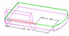
- Start with a shallow Box, or a Simple Extrude based on a polyline or rectangle.
- Activate Flange. Select the face to which you want to add the flange.
- The next click defines the linear edge about which the flange will bend.
- The next click defines how far from one end the flange will start. This distance can be zero. The total length of the edge is also indicated.
- The next click defines how far from the other end the flange will end.
- These distances are Start flange position and End flange position, which can be set in the Inspector Bar as well. You can also define the Radius and Angle here.
The Neutral Depth is the distance into the depth of material, along which there will be no tension or compression. Flange Length is the length of the new material beyond the edge. The preview shows how the final result will look. You can still make changes to all values in the Inspector Bar.
- Select Finish from the local menu or Inspector Bar to complete the flange.
You can use this tool multiple times on the same sheet.
Sheet Metal
Following options are now available in TurboCAD
Taper Angle: Allows to create a flange with one or two tapered side faces
Offset distance dStart and dEnd.
Tube Bend
Default UI Menu: Modify/Modify 3D Objects/Bending/Tube Bend
Ribbon UI Menu:

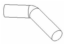
Bends a solid (ACIS) cylinder.
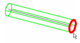
- Start with a cylinder, and activate Tube Bend. Select the cylinder you want to bend. The next click defines the distance where the bend will start.
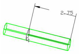
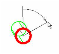
- This distance is the Axial distance, which can be set in the Inspector Bar as well. You can also define the Radius and Angle here.
- The next click defines the direction of the bend, relative to the axis of the cylinder.
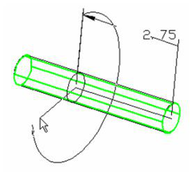
The preview shows how the final result will look. You can still make changes to all values in the Inspector Bar.
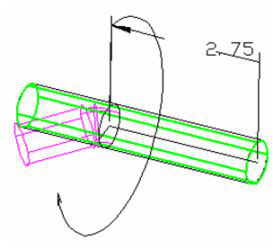
- Click Left Side if you want to bend the cylinder from the other end.
- Select Finish from the local menu or Inspector Bar to complete the bend.
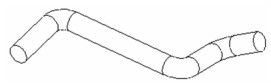
You can use this tool multiple times on the same tube.
Tube Flange
Default UI Menu: Modify/Modify 3D Objects/Bending/Tube Flange
Ribbon UI Menu:

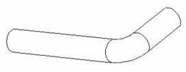
Adds a bend onto a solid (ACIS) cylinder.
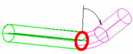
- Start with a cylinder, and activate Tube Flange. Select the cylinder you want to bend. The next click defines the end where the flange will be added.
- The next click defines the, which defines the direction of the bend, relative to the axis of the cylinder.
- This angle can be set in the Inspector Bar as well. You can also define the Radius and Angle here.
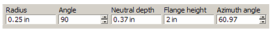
The Neutral Depth is the distance into the depth of material, along which there will be no tension or compression. Flange Length is the length of the new material beyond the current end of the cylinder. The preview shows how the final result will look. You can still make changes to any value in the Inspector Bar.
- Select Finish from the local menu or Inspector Bar to complete the bend.
- You can use this tool multiple times on the same cylinder.
Unfold Face
Default UI Menu: Modify/Modify 3D Objects/Bending/Unfold Face
Ribbon UI Menu:

Unfolds faces of an ACIS object. This is also knows as obtaining the involute of a surface.
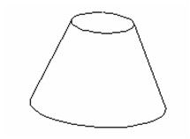
Example 1
- For a simple example, start with a truncated cone, using the Cut Cone by Plane option.
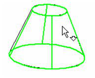
- Activate Unfold Face. Click when the curved face is highlighted. Only faces that can be unfolded will be highlighted.
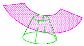
- A preview of the unfolded face will appear.
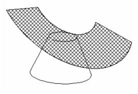
- To create the face, select Finish from the Inspector Bar or local menu.
Example 2
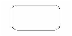
- For a more complex example, start with a Rectangle, filleted using the Fillet tool.
- Create a cone from this polyline, using the Specify 2D Base option.

- Create some cylinders and use 3D Subtract to remove them from the cone.

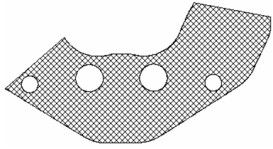
- Activate Unfold Face and click the cone.
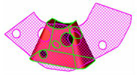
- Select Finish. If you move or delete the cone, you can see the unfolded face clearly
Unbend Sheet
Default UI Menu: Modify/Modify 3D Objects/Bending/Unbend Sheet
Ribbon UI Menu:

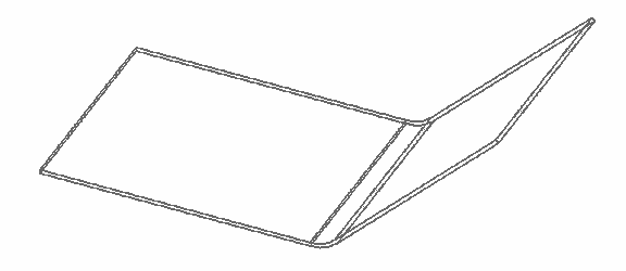
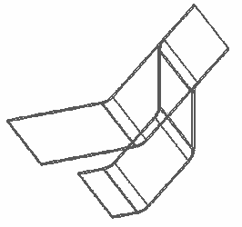
This tool unbends a sheet that has a bend or flange.
It may be used on bends created via filleted corners if the difference in the Radii of the inner and outer fillet equals the depth (thickness) of the material.
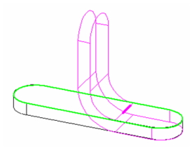
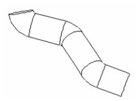
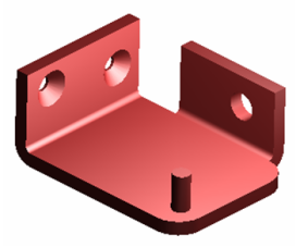
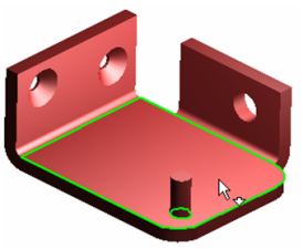
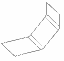
- Start with a sheet that has a bend and/or flange. This example has a sheet with a cylindrical imprint, a bend with two holes, and a flange with one hole.
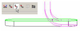
- Activate Unbend Sheet. The Neutral Depth is the distance into the depth of material, along which there will be no tension or compression. Changing this parameter will very slightly affect the resulting sheet size.

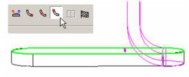
- Select the face that will be used as the base for unbending. The resulting flat sheet will be flushed with this face.
- A preview of the resulting sheet will appear.
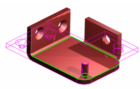
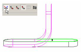
- Select Finish from the local menu or Inspector Bar. The new, unbent sheet is created, overlapping with the base face.
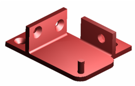
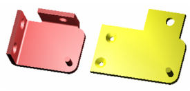
- To see the results, you can move the unbent sheet, or delete the original sheet.
 There are several options available for the Unbend Sheet tool.
Leave Source Copy: if this option is on, the tool leaves the original bent object in place and creates a new unbent object.
There are several options available for the Unbend Sheet tool.
Leave Source Copy: if this option is on, the tool leaves the original bent object in place and creates a new unbent object.
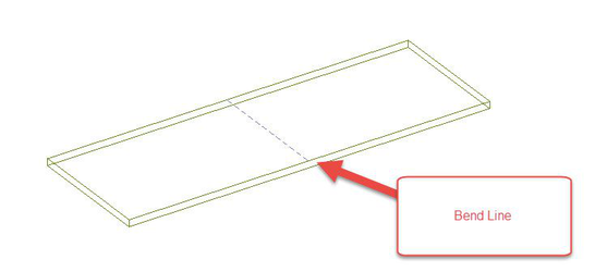
 Get Bend Lines: If this option is on, the tool creates the bend lines that were necessary to create the object. This allows for re-bending if required.
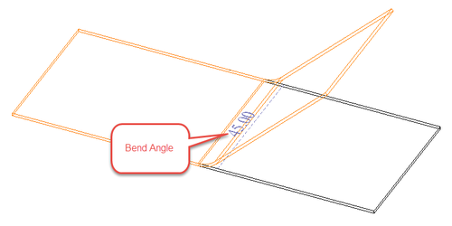
 Get Bend Angle: If this option is on, the tool creates the text representing the bend angle that was, necessary to create the object. This allows for re-bending if required.
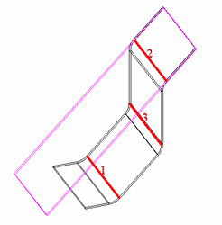
 Unbend along edge: If this option is on, you can individually select edges to be unbent. If this option is off the Unbend tool will unbend everything on the object at once.
 Show Labels: Shows labels designating the order in which edges have been selected for unbending.
Progress Indicator
You can trace the progress of Unbending by progress indicator.

Press "esc" to interrupt the process while building a preview.
Warning box:

Greater accuracy in the "Unbend" results due to using ACIS® unbend at each step.