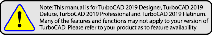
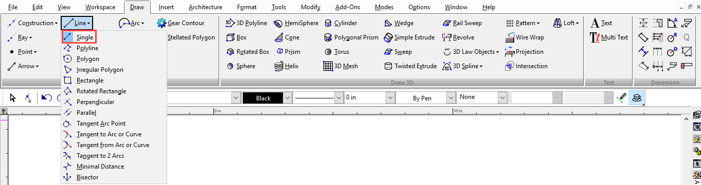
Line
(Available in all TurboCAD Variants)
Default UI Menu: Draw/Line
Tools for drawing lines and linear objects. You can display the Line toolbar by right-clicking in any toolbar area and selecting Line.
Ribbon UI Menu:
LTE Type Objects
 In the LTE Workspace 2D tools behave with slight differences to standard TurboCAD methods.
- They allow use of dynamic input.
- They automatically drop when the action is completed, whereas standard TC tools continue until you change the tool.
- They have a Multiple option (local menu) that turns off auto-dropping for the individual tool.
- You can complete drop the tool by pressing the either the Enter or Space keys.
- You can re-activate the tool by pressing the Space Key again.
With the exception of the Single line tool, all LTE Workspace Line tools work exactly as the equivelant TC tools except as noted in the above list.
Bisector
Default UI Menu: Draw/Line/Bisector
Ribbon UI Menu:

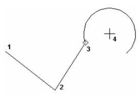
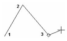
The Bisector line allows you to create a line which bisects an angle. It has two modes: By two lines, and by three points. By two lines:
- Click on the first line.
- Click on the second line
- Click between the two lines.
- Drag and click to create a length or type a value into the Length field and press Enter.
By three points:
- Click on the first point. this will be the first edge of the angle to be bisected.
- Click on the second point. this will be the vertex of the angle to be bisected.
- Click on the third point. this will be the second edge of the angle to be bisected.
- Drag and click to create a length or type a value into the Length field and press Enter.
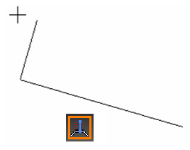
Irregular Polygon

Default UI Menu: Draw/Irregular Polygon
Ribbon UI Menu:

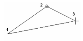
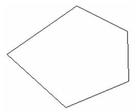
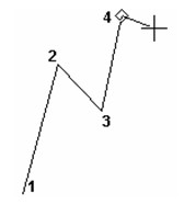
Creates a polygon (closed) with irregular sides and angles. This is equivalent to using the Polyline tool to create line segments in "closed" mode.
- Define the first two vertices, creating the first segment. You can also use the Inspector Bar to enter a length and angle.
- Define the next segment. From this new vertex, a closing segment is created back to the first vertex.
3. Create as many segments as needed. A closing segment is always created from the last vertex.
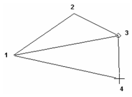
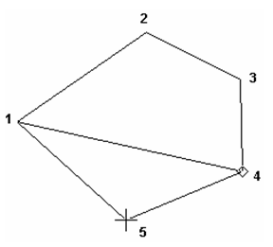
4. Select Finish from the local menu or Inspector Bar, or press Alt+F.
Note: To undo polygon segments in reverse order, select One Step Back from the local menu or Inspector Bar (or press Backspace).
Options Fillet Corners: If this option is turned on a the corners of the polygon will be rounded by filleting. A Radius F field appears in the Inspector bar that allows you to specify the radius of the fillets.
Minimal Distance

Default UI Menu: Draw/Line/Minimal Distance
Ribbon UI Menu:

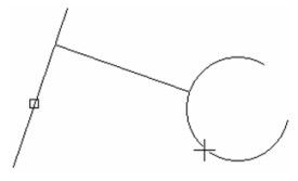
Creates the line representing the shortest distance between two 2D objects. The objects must be on the same workplane.
- Select the first object from which you want to draw the shortest line.
2. Select the second object.
3. The shortest-distance line is created.
Local menu options:
Through Point: Creates a line passing through a specified point. The through point should only be specified for one of the objects, otherwise a standard single line is created.
 Show beforehand displays the shortest line to an object when you pass the cursor over it. This allows you to preview the line before creating it.
Parallel

Default UI Menu: Draw/Line/Parallel
Ribbon UI Menu:

Creates a line parallel to a existing line.
- Select an existing line.
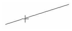
2. Select the location of the parallel line, or enter the offset in the Inspector Bar. By default, the parallel line will have the same length as the original line.
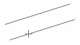
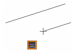
Local menu option: Keep Length (default): If not used, you can create a parallel line with a different length than the original line. You can only adjust one endpoint of the line - the endpoint closest to where you selected the original line. You can enter both the offset and length in the Inspector Bar.
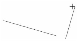
Perpendicular
 Creates a line perpendicular to an existing line.
Default UI Menu: Draw/Line/Perpendicular
Ribbon UI Menu:

Tip: This tool creates a line from an existing line. To create a perpendicular line to a line, you can use the "J" SEKE
- Select an existing line.
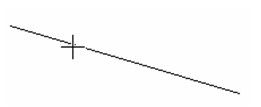
- Select the point on the existing line where the perpendicular line will start. You can select a point past the endpoints.
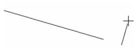
- Select a third point to set the length of the perpendicular line, or enter the length in the Inspector Bar.
Local menu option:
Limit to Segment: The perpendicular line cannot extend past the endpoints of the existing line.
Tip: To draw a line perpendicular to an arc or circle, draw a single Line from the center of the arc or circle to its destination, then trim the line.
Polygon

Default UI Menu: Draw/Polygon
Ribbon UI Menu:

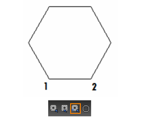
Creates a regular (equal-length sides) polygon.
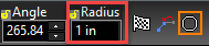
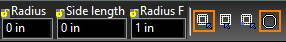
- Enter the number of sides in the Inspector Bar. If desired, you can also specify the Angle (angle of control point from the center), and Radius or Side (length of one side).
- Select the mode: Vertex, Segment or Edge.
- If you are using Vertex or Segment mode, select the polygon centerpoint.
- Use the Segment Mode from the local menu or Inspector Bar to use the midpoint of one segment as a control point.
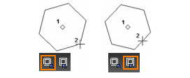
- Or, select Edge Mode from the local menu or Inspector Bar to use the midpoint of one segment as a control point.
Options
Fillet Corners: If this option is turned on the corners of the polygon will be rounded by filleting. A Radius F field appears in the Inspector bar that allows you to specify the radius of the fillets.
 Create Pattern Constraint: (Mechanical Edition Only) If this option is turned on a pattern constraint will be created from the resulting polygon. Auto Add Constraints must be turned on for this feature to work.
Polyline
Default UI Menu: Draw/Polyline
Ribbon UI Menu:

Creates a series of connected straight line or arc segments that comprise one object. The segments can have different and/or tapered line widths.

Note: If you want to create a polyline by joining a series of existing line or arc segments,
- By default, line segments are created (as opposed to arcs). Select each endpoint, or enter segment lengths and angles in the Inspector Bar.
Note: You can choose to enter an Angle which is absolute in relation to the world or a Relative Angle which is the angle from the immediately previous segment (arc or line).
2. To draw arc segments, select Arc Segment from the local menu or Inspector Bar.
3. By default, each arc segment is tangent to the previous segment, but the tangency can be changed via the local menu options. Select each arc endpoint, or enter parameters in the Inspector Bar. 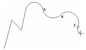
4. To switch back to lines, select Line Segment from the local menu or Inspector Bar.

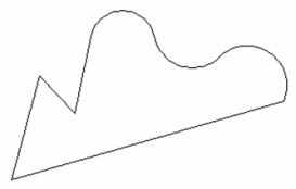
5. When all segments are created, select Finish (Alt+F) from the local menu or Inspector Bar, or double-click the last point. If you want to create a line or arc segment connecting the first and last points, select Close (Alt+C).
Local menu options (Arcs):
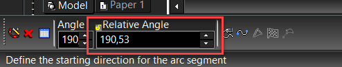
Direction: Rather than creating an arc segment tangent to the last segment, you can set the start angle of the arc segment.
After selecting Direction, you can set an Angle which is absolute in relation to the world and a Relative Angle which is the angle from the immediately previous segment.
- For the arc segment, move the mouse to set the start angle, or enter the angle in the Inspector Bar.
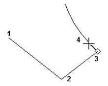
- Select the arc endpoint, or enter its parameters in the Inspector Bar. The next arc segment you create will revert to the default - tangent to the previous segment.
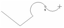
Center: Rather than creating the arc tangent to the last segment, you can set the start angle and size by selecting the arc center. 
- For the arc segment, select the arc center, or enter the arc length in the Inspector Bar.
- Size the arc by selecting its endpoint, or enter its angle or arc length in the Inspector Bar.
- The next arc segment you create will revert to the default - tangent to the previous segment.
Polyline Line Widths
. By default, polyline segments have the default line thickness (which can be set in the Pen Width box on the Property toolbar.)
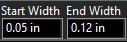
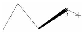
For any segment, you can enter values for Start and End Width.
The next segment will have these properties, but the subsequent segments, by default, will revert to the default thickness.
To change the widths of adjacent segments you can open the Polyline Properties from the local menu or Inspector Bar.
 In this window, you can force start and end widths to be equal, and to set the start width of each segment to be equal to the end width of the previous segment.
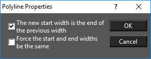 Activate both options if you want to apply a uniform thickness to the entire polyline, or to a contiguous group of segments.
Note: If you use Start and End Width to create a segment with tapering thickness, this taper will be lost when the polyline is exploded, and then the tapered segment is exploded.
Rectangle

Default UI Menu: Draw/Rectangle
Ribbon UI Menu:

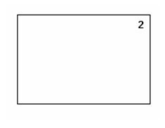
Creates an orthogonal rectangle by defining two diagonally opposite corners.
- Select the first corner.
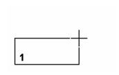
- Select the diagonally opposite corner. You can also enter the size in the Inspector Bar.
Options
Fillet Corners: If this option is turned on a the corners of the polygon will be rounded by filleting. A Radius F field appears in the Inspector bar that allows you to specify the radius of the fillets.

Rotated Rectangle

Default UI Menu: Draw/Rotated Rectangle
Ribbon UI Menu:

Creates a non-orthogonal rectangle.
- Select two points to define the base. The angle of this line defines the orientation of the rectangle.
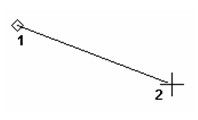
2. Define a third point that specifies the distance from the base to the top.
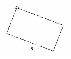
You can also enter the length of both sides and the orientation angle in the Inspector Bar.
Options
Fillet Corners: If this option is turned on a the corners of the polygon will be rounded by filleting. A Radius F field appears in the Inspector bar that allows you to specify the radius of the fillets.

Single Line

Default UI Menu: Draw/Single
Ribbon UI Menu:
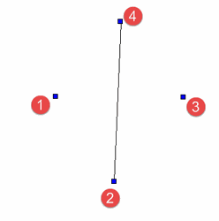
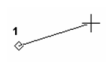
Creates a single line segment.
- Define the segment start point.
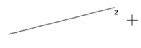
- Define the endpoint, or specify the length and angle in the Inspector Bar.
LTE Workspace
In the LTE Workspace the line tool creates a series of discrete line segments until you select Finish, or close from the local menu (or Command Line) or until you press the either the Enter or Space keys.

Tangent Arc Point

Default UI Menu: Draw/Line/Tangent Arc Point
Ribbon UI Menu:
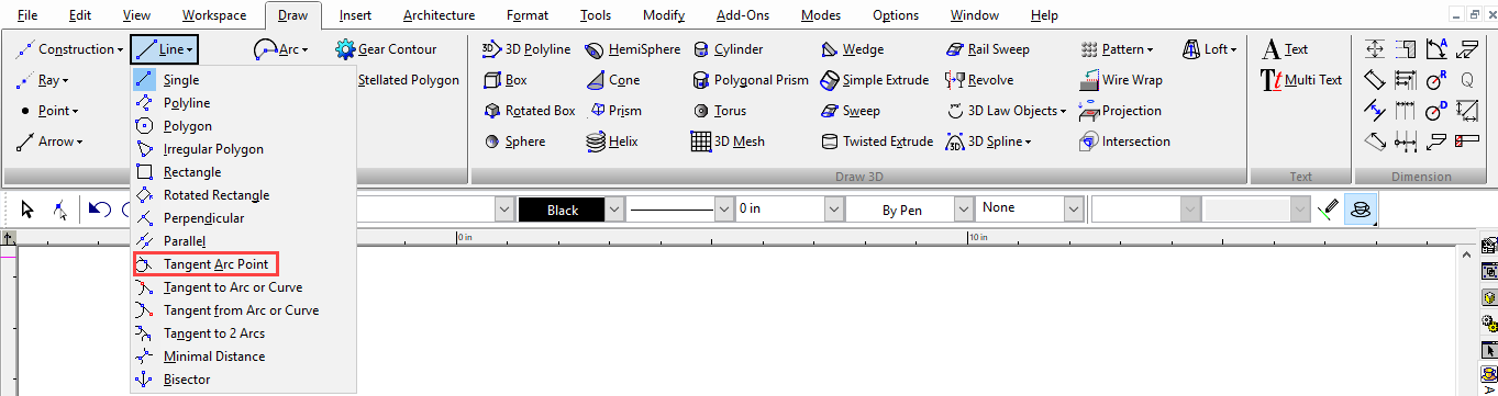
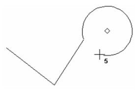
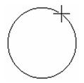
Creates a line tangent to an arc, circle, or ellipse, with the midpoint of the line located at the point of tangency.
- Select the tangent arc, circle, or ellipse.
- Move the mouse to adjust the length of the line, or set the length in the Inspector Bar. The line midpoint always remains at the tangent point.
- Move the mouse to change the angle of the line and the point of tangency, or set the angle in the Inspector Bar.
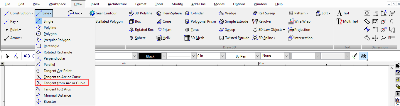
Tangent from Arc

Default UI Menu: Draw/Line/Tangent from Arc or Curve
Ribbon UI Menu:
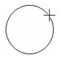
Creates a tangent line from an arc, circle, or ellipse.
- Click on the side of the arc or circle from which you want to draw the tangent line.
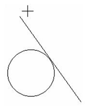
- A tangent line appears from the selected point. Click to set the length, or enter the length in the Inspector Bar.
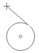
- Move the cursor to set the line angle, or enter the angle in the Inspector Bar.
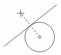
To switch the side of the tangent line, pass the cursor through the tangency point.
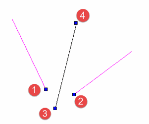
Tangent to 2 Arcs
Default UI Menu: Draw/Line/Tangent to 2 Arcs
Ribbon UI Menu:
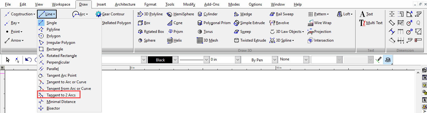
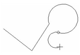
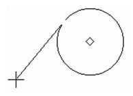
Creates a line tangent to two arcs or circles.
- Select one of the tangent objects - arc, circle, or ellipse.
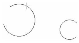
-
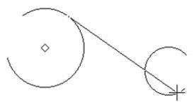
The tangent line extends from this object. To switch the side of the line, pass the cursor through the point of tangency. Adjust the line so that it is close to the desired point of tangency.
-
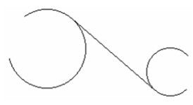
Select the second tangent object, close to the point of tangency. The tangent line is created.
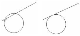
Tangent to Arc
Default UI Menu: Draw/Line/Tangent to Arc or Curve
Ribbon UI Menu:
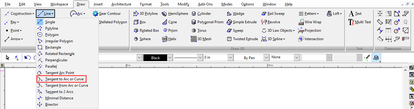
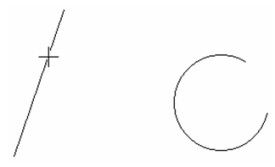
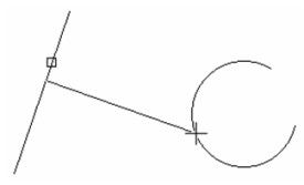
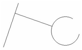
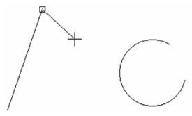
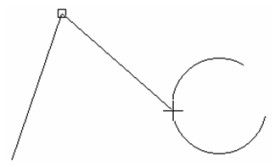
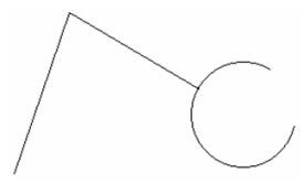
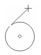
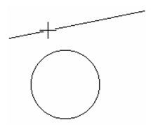
Creates a line tangent to an arc, circle, or ellipse, starting from a selected point.
- Select the start point of the line.
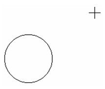
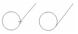
- Select the tangent arc, circle, or ellipse, close to the point of tangency. The tangent line is created.
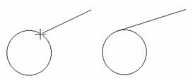
In this example, clicking on the other side of the circle would have created a different tangent line.
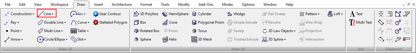
Tangent Line of Fixed Length
By default, Tangent to Arc creates a line from the start point, ending at the tangent object. To fix the length of the line, enter the length in the Inspector Bar and lock it, but do not press Enter. When you move the cursor, the line length remains constant.
Select the tangent object, close to the point of tangency. The fixed-length tangent line is created.