Dimensions
(Available in all TurboCAD Variants)
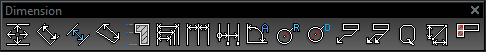
Default UI Menu: Dimension
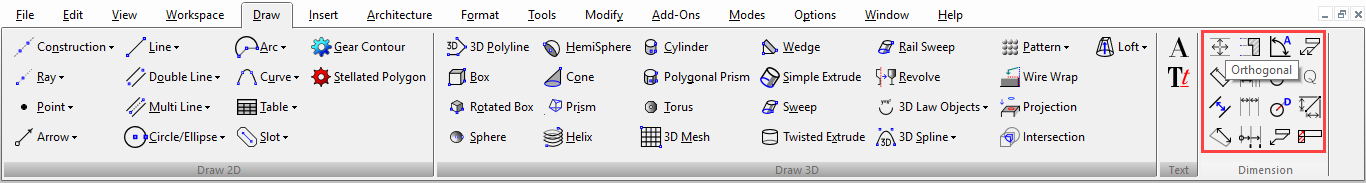
Ribbon UI Menu:
TurboCAD contains a variety of dimension tools that you can use to display the measurements of lines and angles.
 Dimensions consist of three basic components:
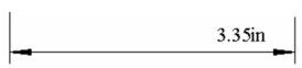
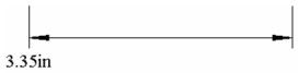
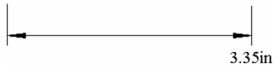
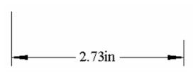
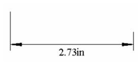
Dimension lines, with arrows pointing to either end of the dimension. A linear dimension can have an interior dimension line or two exterior dimension lines. Exterior dimension lines can be supplemented with an optional interior line.
Extension lines, which connect the dimension line to the object being dimensioned. Extension lines have optional line segments that continue the extension outward beyond the dimension line (extensions to the extension).
Dimension text, typically displaying the distance being dimensioned in World units.
Dimensions consist of three basic components:
Dimension lines, with arrows pointing to either end of the dimension. A linear dimension can have an interior dimension line or two exterior dimension lines. Exterior dimension lines can be supplemented with an optional interior line.
Extension lines, which connect the dimension line to the object being dimensioned. Extension lines have optional line segments that continue the extension outward beyond the dimension line (extensions to the extension).
Dimension text, typically displaying the distance being dimensioned in World units.
Note: For information on editing dimensions, . To create a group of dimensions automatically, To constrain dimensions,
Associative Dimensions
(Available in Platinum)
When a dimension is associated with objects, you can freely move, rotate, or resize the associated objects and the dimension will retain its position relative to the objects, and the dimension text will change automatically to reflect changes.
Note: To make dimensions associative to other dimensions,
Before creating associative dimensions, associativity needs to be activated in the default Properties of the dimension tools. Associativity cannot be set in the Properties window of a selected dimension; this parameter must be set before the dimension is created. Right-click on any dimension tool to bring up the Properties window, and open the Format page. Make sure that Associative Dimension is checked.
Tip: To tell whether a dimension is associative, select the object. Any dimensions associated with that object will be colored blue.
There are the following limitations on associativity:
Dimension cannot be associative if you override the automatic dimension text, either in the Inspector Bar or in the Attribute field of the General page of a dimension's Properties.
Datum dimensions cannot be associative. However, grouping datum dimensions with their objects can achieve a similar effect to associative dimensioning. Be sure to explode to edit objects later.
The following dimensions will only be associative if originally created using Snap to Vertex or Snap to Center, or if created using Segment or Entity Dimensioning: Baseline, Continuous, Incremental, Leader Orthogonal, Parallel.
When dimensioning over a Viewport in Paper Space, the dimensions will associate with the viewport itself, but not with the corresponding objects in Model Space.
To break the associativity between a dimension and its objects, select both the object(s) and the dimension. Right-click and select Drop Link from the local menu.
Creating Dimensions
(Available in all TurboCAD Variants)
Creating dimensions involves two basic steps: selecting the objects to be measured, and locating the dimension. By default the magnitude of the dimension is calculated automatically and is recorded as the dimension text, measured in current World units. (Leader dimensions, which contain text labels, are the exception to this rule.) You can override the default text of a dimension by specifying the text in the Inspector Bar prior to finishing the dimension.
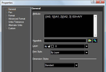
 You can also change the dimension text in the dimension's Properties, by changing the Attributes field of the General page.
Note: To create several types of dimensions automatically in one step,
When Auto Add Constraints is active, any dimensions you assign are created as variables that appear in the Calculator Palette.

Dimension variables can be constrained to other dimensions, or to other variables or numbers. This is particularly powerful when used in conjunction with Auto Constraints See
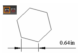
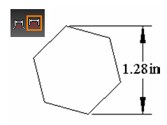
Orthogonal Dimension
Creates a horizontal or vertical dimension.
Note: To create orthogonal dimensions automatically,
- Select the first point.
- Select the second point, or enter the length and angle of the dimensioned line in the Inspector Bar.
- For a horizontal dimension, move the mouse above or below the two points and click to define the location. You can also enter the length of the witness lines in the Inspector Bar.
- For a vertical dimension, define the dimension at either side of the two points.
Local menu options: Segment Dimensioning, Entity Dimensioning Horizontal / Vertical Mode only: creates either type of dimension, no matter where the dimension is located.
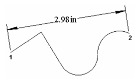
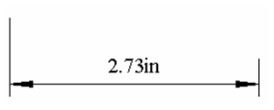
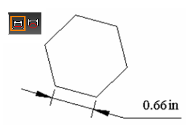
Parallel Dimension
Creates a dimension showing the absolute length of an object.
Note: To create parallel dimensions automatically,
- Select the first point.
- Select the second point, or enter the length and angle of the dimensioned line in the Inspector Bar.
- Move the mouse and click to define the location. You can also enter the length of the witness lines in the Inspector Bar.
For any two endpoints, the absolute length is parallel to the line between the points.
Local menu options: Segment Dimensioning, Entity Dimensioning
Distance Dimension
Sets two lines parallel to one another and places a constrained dimension between them. For this tool to be available, Auto Add Constraints must be on.
Note: To create distance dimensions automatically,
- Select the two lines, or select them by snapping to either of their endpoints.
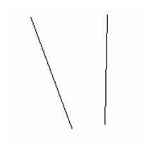
- Place the dimension, and the lines are made parallel.
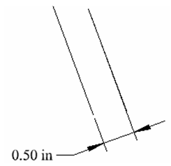
Note:Because Auto Add Constraints is on, the Distance dimension appears as a variable in the Calculator Palette and can be edited.
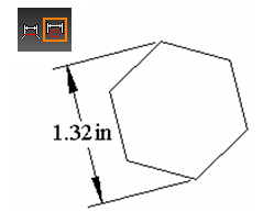
Rotated Dimension
Creates a dimension projected in a specified direction.
- Select two points to define the dimension's direction. The dimension will be measured normal to this line. You can also define the first point, then specify the angle of the vector in the Inspector Bar.
- Select the first point of the object to be dimensioned. Select the second point, or enter the length and angle of the dimensioned line in the Inspector Bar.
- Move the mouse and click to define the location. You can also enter the length of the witness lines in the Inspector Bar.
Local menu options: Segment Dimensioning, Entity Dimensioning: Available only after the dimension direction has been defined.
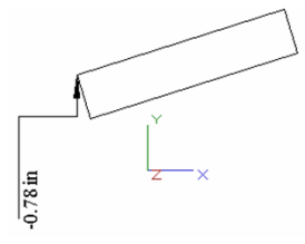
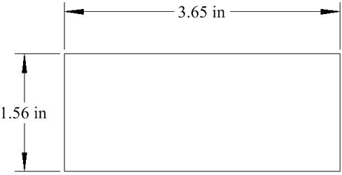
Datum Dimension
Creates a dimension showing the horizontal or vertical distance from a point. By default, the point is the absolute origin, but you can change this.
- Select the point whose distance from the origin is to be displayed. A rubberband line appears, indicating the origin of the dimension.
- To display the Y coordinate (horizontal dimension text), move the mouse to either side of both the origin and the selected point, and click to locate the dimension. You can also enter the angle and length of the extension lines in the Inspector Bar.
- To display the X coordinate (vertical dimension text), move the mouse above or below both the origin and the selected point.
Local menu options: Set Origin: By default, datum dimensions are created relative to the absolute origin. Use Set Origin to select a new origin. This origin will remain in effect until changed.
Baseline Dimension
Creates a series of parallel linear dimensions that follow the axis of an existing linear dimension.
- Select an existing linear base dimension. Click near the side you want to serve as the baseline. A temporary rectangle appears at the baseline end.
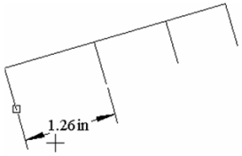
- Select the first point where you want a new baseline dimension.
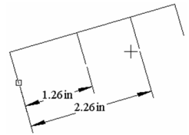
- Continue selecting points. Each new baseline dimension will be created at an offset from the previous one.
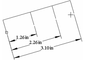
Note: The offset distance is controlled by the Baseline Increment value on the Advanced Format page of the Properties window.
When finished, select Cancel from the local menu or press Esc. Local menu option: Select Dimension: Select a new base dimension.
Continuous Dimension
Creates a series of parallel linear dimensions measured from the previous dimension. The dimensions follow the axis of the base dimension.
- Select an existing linear base dimension. Click near the side you want the next dimension to be created. A temporary rectangle appears at the baseline end.
- Select the first point where you want a new continuous dimension.
- Continue selecting points. Each new continuous dimension will be measured from the previous dimension.

- When finished, select Cancel from the local menu or press Esc.
Local menu option: Select Dimension: Select a new base dimension.
Incremental Dimension
Creates a series of parallel linear dimensions measured from the previous dimension. The dimensions follow the axis of the base dimension, and are displayed normal to the axis.
- Select an existing linear base dimension. Click near the side you want the next dimension to be created. A temporary rectangle appears at the baseline end.
- Select the first point where you want a new incremental dimension.
- Continue selecting points. Each new incremental dimension will be measured from the previous dimension.
- When finished, select Cancel from the local menu or press Esc.
Local menu option: Select Dimension: Select a new base dimension.
Angular Dimension
Creates dimensions measuring angles. You can dimension the angle between two lines, the angle of an arc, between two points of a circle, and between a node and two points.
Note: To create angular dimensions automatically,
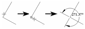
Angle Between Two Lines
- Select the two lines.
- Move the mouse to dimension the acute or obtuse angle. Click to locate the dimension, or enter the length and angle in the Inspector Bar.
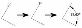
Be careful where you select the lines. If you select close to the angle vertex, you could dimension the complementary angle.
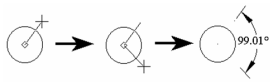
Angle within a Circle
- Select the circle.
- Select the start angle, or enter the angle in the Inspector Bar.
- Select the end angle.
- Move the mouse to dimension the acute or obtuse angle. Click to locate the dimension, or enter the length and angle in the Inspector Bar.
Angles of an Arc
- Select the arc.
- Move the mouse to dimension the acute or obtuse angle. Click to locate the dimension, or enter the length and angle in the Inspector Bar.
Note: If Arc Length is checked in the Format page of the Properties window, the arc length will be dimensioned instead of the angle.
Local menu option:
Angular Dimension option is avalaible in local menu
Angle Node (freeform angle): Dimensions an angle by selecting the angle vertex then two points.
- Select the angle vertex of 2D entity.
2.Define the first angle endpoint.
3.Define the second angle endpoint.
After clicking the second angle endpoint, the obtuse Angle Node dimension is displayed. To see the acute Angle Node dimension move your mouse cursor down away from the display of the Obtuse Angle Node Dimension
Radius - Diameter Dimension
Dimensions the radius or diameter of an arc or circle.
Note: To create radius or diameter dimensions automatically,
- Select the arc or circle.
2. Move the mouse and click to locate the dimension, or enter the length and angle in the Inspector Bar.
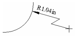
Local menu option: Large Radius: If the arc center is out of your drawing space, use this option to display the dimension from outside.
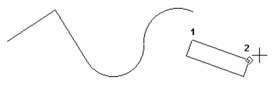
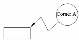
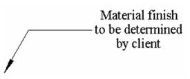
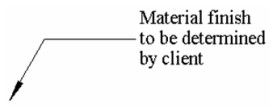
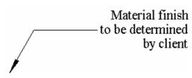
Leader
Creates dimension text attached to a simple line leader pointing to a location in your drawing. The leader is similar to a polyline.
Note: Check Draw as Spline on the Advanced Format page of the Properties window to create a curves leader rather than line segments.
- Enter the text in the Inspector Bar.
- Select the leader start point (the end with the arrow). Select or more additional segment endpoints, or enter the length and angle of each segment in the Inspector Bar.----
Note: The arrowhead is defined by Arrowheads / 1st on the Format page of the Properties window.----
3. Double-click to finish, or select Finish from the local menu, or press Alt+F.
A text box can be created, by selecting one from the Advanced Format page of the Properties window.
Wall Dimensions
There is a special tool for dimensioning walls created via the Architecture tools.
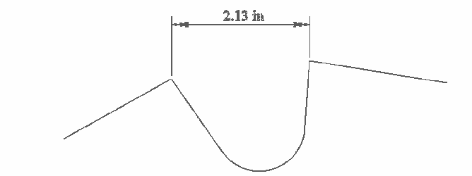
Move Text for Dimensions
(Available in Platinum)
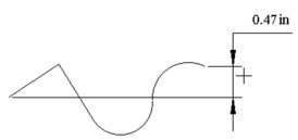
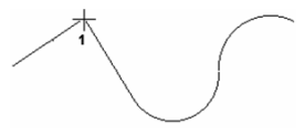
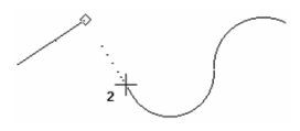
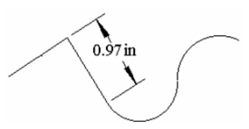
The orthogonal, Parallel and Rotated dimension tools have a feature called Move Text available from the Local menu and the Inspector bar.
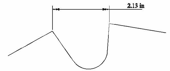
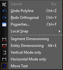 When this option is selected a final step is added. After the dimension is placed the user can drag the text to an offset position.
Click to set the final position for the text.
When this option is selected a final step is added. After the dimension is placed the user can drag the text to an offset position.
Click to set the final position for the text.
Dimension Properties
(Available in Platinum)
Controls the format of dimensions. You can set the properties for all dimensions, or for just a single dimension.
Text
There is no Text page in dimension Properties, but parameters can be set in the Selection Info palette. For details on Text parameters.
Format
Controls the shape of dimension arrows and the position of text relative to the dimension line.
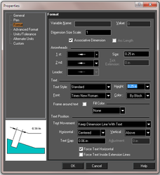
Variable Name and Value: If the dimension is produced as a result of Auto Dimensions (most commonly used together with Auto Constraints), the dimension will have a variable name and value assigned to it. This value appears in Properties / Format window, as well as the Calculator Palette.
Note:
Dimension Size Scale: The scaling factor for displaying the dimension. Arc Length: Available for Angular dimension, displays the arc length rather than degree measurement. Associative Dimension: Checked by default. Associative dimensions retain their positions and the dimension text will update when their associated object changes. To tell whether a dimension is associative, select the object. Any dimension associated with the object will be colored blue.
Note: This parameter is only available when setting the default properties of dimension tools . You will not see it in the Properties window for a selected dimension. This parameter must be set before the dimension is created.
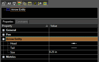
Arrowheads:
1st and 2nd: Select arrow shapes for the start and end of the dimension.
Leader: Select the arrow shape for leader dimensions.
Size: Length of the arrowhead or diameter of the dot
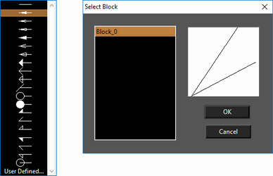
Tick Extension: specify the length of the tick extension line. You can specify a custom user defined arrowhead. User defined arrow heads are based by selecting a block.
Text:
Text Style: Select the Text style for the dimension. Text styles are specified in the Style Manager. Height: Sets the height of the dimension text. Font: Specifies the font use in the dimension text. Color: Sets the color of the dimension text. Frame around text: Draws a rectangular frame around the dimension text. Fill Color: Specifies a color which will fill the text frame. The options are: None, Background and Custom. Background fills the frame with the background color. Custom allows you to select a color. Text Position: Controls the dimension text position: Text Movement: These options control how the dimension text is moved when editing the dimension. See [] Horizontal: Select the text alignment with respect to witness lines. The preview window displays each option. Options vary for dimension and leader text.
 Dimensions - Centered
Dimensions - First Extension Line
Dimensions - Second Extension Line
 Dimensions - Over First Extension Line
 Dimensions - Over Second Extension Line
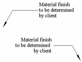 Leaders - Default Justification(Depends on the leader orientation)
 Leaders - Center Justification
 Leaders - Left Justification
 Leaders - Right Justification
Vertical: Select the text alignment with respect to the dimension/leader line. Outside places the text on the side of the dimension/leader line opposite the selected dimension/leader points.
Leaders - Right Justification
Vertical: Select the text alignment with respect to the dimension/leader line. Outside places the text on the side of the dimension/leader line opposite the selected dimension/leader points.
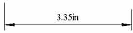
 Above
Above
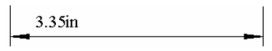
 On Line
 Outside
Text Gap: The distance between the dimension text and the dimension line. Adjustment: Available for VerticalOnLine position, The distance of the text above or below the dimension line. A value of zero (default) will place the text on the same level as the dimension line. Higher values move the text above the line; lower (negative) values move the text below the line. Force Text Horizontal: Makes the dimension text horizontal no matter how the dimension is rotated. Force Text Inside Extension Line: Keep dimension text between the extension lines, regardless of the distance between the extension lines. If unchecked, the system will decide where to place text.
Non-Rotatable Text
With a dimension (or dimension tool) selected, you can go to the Selection Info palette, and under the Text-Transformation area you can specify that the text be non-rotatable.
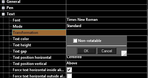
When text is set to non-rotatable it will always face the user no matter the orientation of the drawing.

Advanced Format
Options for drawing and scaling the dimension and extension lines.
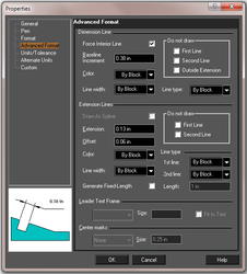
Dimension Line:
The line over which the dimension text is located. Force Interior Line: If checked, the dimension will have an interior dimension line even if the text is outside the extension lines. If unchecked, the interior dimension line will be drawn only if the dimension text is inside the extension lines. Baseline Increment: The distance between each dimension in a series of baseline dimensions. Do not Draw: Options for omitting parts of the dimension line. Color: Sets the color of the dimension line. Line Width: Sets the Line width for the dimension line. Line Type: Specifies the line type for the dimension line.
Extension Line:
Lines that connect the dimension line to the object being dimensioned. Draw as Spline: If checked, the Leader tool will use a spline rather than a line to attach the dimension text to the corresponding drawing location. Extension: The length of the extension line segments that extend outward beyond the dimension lines. Offset: The distance between the extension lines and the dimensioned object. Do not Draw: Options for omitting parts of the extension lines. Color: Sets the color of the extension lines. Line Width: Sets the line width for the extension lines. Line Type: Specifies the line type for the extension lines. Generate Fixed-Length – Use the Length field to fix the length of the maximum drawn length for extension lines. Length - Specify the length used by the Generate Fixed-Length property.
Leader Text Frame:
Available only for Leader dimensions. Select a shape for the closed line bounding the dimension text. Size: When Circle or Quadrate is selected for the text box, define the box size. Fit to Text: Check if you want the text box to fit the dimension text.
Units - Tolerance
Parameters for formatting the appearance of dimension text, and for controlling the display of tolerance - the allowable deviation from the dimension.
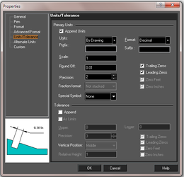
Primary Units:
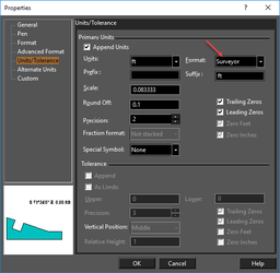
Append Units: If checked, the dimension text will display its unit. Units: If Append Units is checked, select the desired units. Format: Options for how the dimension text is displayed (decimal, feet, radians, surveyor, etc.) As of version 2015 the Format setting can now be set to By Drawing. This means the format used will be the one globally specified on Options | Space Units Prefix, Suffix: Add a prefix and/or a suffix to the dimension text. (Not available for Leader dimensions.) Scale: Change the scale of the value displayed by the dimension text relative to World units. For example, if you enter a value of 0.1, the dimension will display a value of 0.1 inch when dimensioning a distance of 1 inch in World units. The default value for the linear measurement scale is 1.
Note: You will probably want to leave Scale unchanged, unless you have an inset in your drawing that uses a different scale than the rest of your drawing.
Round Off: -The decimal place to which the dimension text will round off. If you type a value of 0.1, for example, the text will be rounded off to tenths. Special Symbol: Prepends a symbol to the dimension text. The options include: None, Diameter, Degree, and Plus Minus. Precision: The level of accuracy, represented by a number between 1 and 10. Trailing Zeros: is set to 4, and and Round Off is set to 4, the dimension text will read 2.3400.
Note: Trailing Zeros, Round Off, and Precision are interrelated, and need to be considered as a group when establishing dimension settings. If Round Off is less than Precision, dimension text may not accurately reflect the exact measurement. If Round Off is greater than Precision, then Trailing Zeros will show the additional available precision if Trailing Zeros is set to a value equal to Precision. For most applications, Precision and Round Off should be set to the same level (a Precision of 4 is the same as a Round Off of 0.0001). Trailing Zeros should then be used if necessary to display the level of precision in use. Trailing Zeros is not applicable when fractions are used.
Leading Zeros: For dimensions of less than one unit, a zero will appear at the beginning of the dimension. For example: 0.5 feet, as opposed to .5 feet. Zero Feet, Zero Inches: Relevant for architectural and engineering units. For dimensions less than one foot or one inch, the zero will appear as a placeholder. For example: 0'-0 1/4" as opposed to 1/4".
Tolerance:
Append: If checked, the dimension text will include a tolerance. As Limits: If checked, the dimension will be shown as a pair of values defining the limits of the dimension value. Relative Height: The height of the tolerance relative to the rest of the dimension text. Upper, Lower: Values for positive and negative tolerance. The remaining tolerance parameters are the same as for Primary Units.
Alternate Units
Alternate units are a secondary set of units for each dimension, such as 1" [25.4mm].
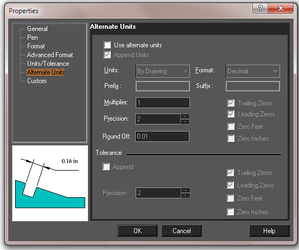 Use alternate units: If checked, the dimension and/or tolerance will be displayed with a value in alternate units, in square brackets following the primary dimension. The parameters are the same as on the Units / Tolerance page.
Dimensions in_through Viewports
(Available in Platinum)
Dimensioning within a viewport in paper space will provide dimensions of the object. The dimensions will be scaled correctly according to the scale of the view. Misleading dimensions can result if the viewport is not exactly parallel to the object. Therefore attempting to dimension an Isometric view by this method is not advised. The dimensions will be associative to model and drawing elements through viewports in paper space layouts. These associative dimensions will update with model and drawing changes. This is automatic, but only applies to the following objects:
- Solid objects
- 2D objects
- Surface objects
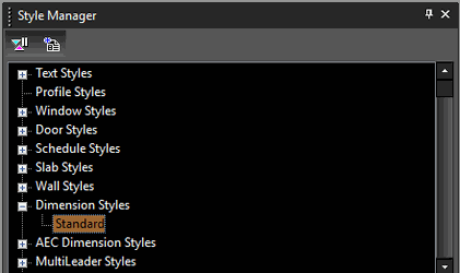
Dimension Styles
You can manage and create dimension styles using the Style manager. For more on the Style Manager see . In the Style Manager, there is one style, "Standard," listed under "Dimension styles.".
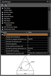
Note: In the Preview area, you can click to zoom part of the graphic. Double-click to fit the graphic in the window.
- You can change the "Standard" style, but if you want to preserve this style, make sure "Standard" is highlighted, then click Create New.
- Assign a name or accept the default.
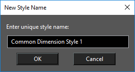
This creates a new which is a copy of "Standard."
- To change the current wall dimension to the new style, open its Properties to the General page.
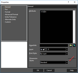
Dimension styles can control all of the properties of your dimensions, They are also automatically imported from DWG files.
Note: While Pasting entity with style, the TurboCAD uses the following merge logic: Let say the source entity Dimension has a source style called "D-Size"
- If the target drawing has no style with the same name - new dimension style is created "D-Size" in the target drawing.
- The target drawing has style with the same name - we compare properties of source and target styles. If the styles are equal nothing is done (target style is used). Otherwise a new style is created with a free default name ("Common dimension style ...") and property values from the source style "D-Size".
Quick Dimensions

Default UI Menu: Dimension/Quick
Ribbon UI Menu:
Creates a series of dimensions on one more objects. You can choose the type of dimension and which points will be included.
Note: To create a group of various types of dimensions automatically,
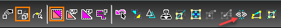
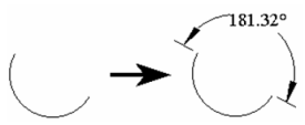
Activate the Quick function, then choose three criteria:
Whether the dimensions will be orthogonal (horizontal / vertical.
The type of dimension (continuous, baseline, etc.),
The points between which the dimensions will be created.
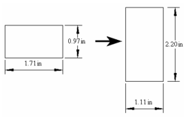
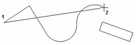
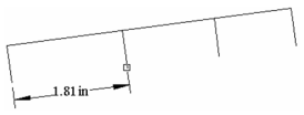
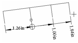
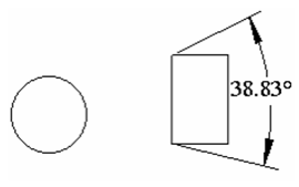
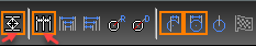
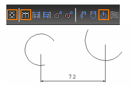
In this example, the dimensions will be Orthogonal and Continuous (indicated by the arrows in the picture below). Points will be described later in the example.
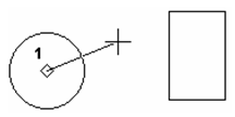
Select the object or objects to dimension. You can use the Shift key to select multiple objects, or drag a selection window. This example consists of one circle and one polyline.
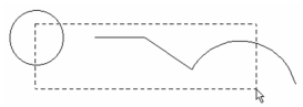
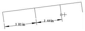
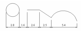
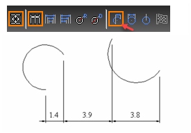
Double-click when all objects are selected. Then move the cursor and click to place the dimensions. Moving the mouse to the right or left of the objects creates vertical dimensions; moving above or below the objects, as shown below, creates horizontal dimensions.
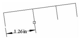
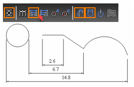
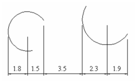
This would be the result with Staggered dimensions:
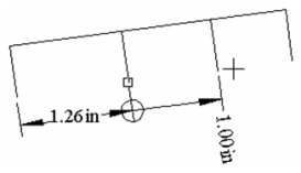
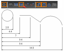
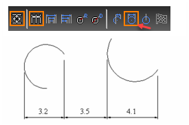
This would be the results with Baseline dimensions.
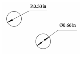
If Radius is selected, a radius dimension is assigned to all arc or circle segments found in the selected objects.
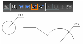
If Diameter is selected, a diameter dimension is assigned to all arc or circle segments found in the selected objects.
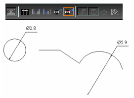
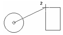
Points affect dimensioning of arcs, curves, and segments of polylines. Start / End creates dimensions between all start and end points of arcs.
Dimension measures the overall distance of the objects.
Arc Center measures between center points.
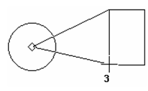
You can combine Points options. This example uses both Dimension and Arc Center.
If Orthogonal is not selected, you can define the dimension direction. Select two points to define the direction normal to the desired dimension line.
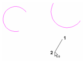
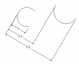
This is the result of non-orthogonal, baseline dimensions.
Segment and Entity Dimensioning
For linear dimensions (orthogonal, parallel, and rotated), you can define the dimension by selecting two points (manually), or you can select a segment or entire object to dimension. Segment and Entity modes are options on the local menu, as well as on the Inspector Bar while using a linear dimension tool. Once you have selected a dimensioning mode, the mode remains in effect until changed.
Tip: If you generally prefer one of the dimensioning modes over the others, you can save it in a drawing template. To do this, use File / Save As to save the file as a .tct file (TurboCAD Template). Place the template file in the "Template" folder of the TurboCAD root directory. Then when you want to open the template, use *File / New, and select New from Template.
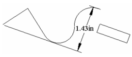
In Segment mode, select any line segment, and the dimension between endpoints is created.
Segment mode - orthogonal dimension
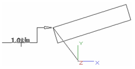
Segment mode - parallel dimension
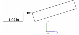
Entity mode - parallel dimension
Smart Dimensions

Default UI Menu: Dimension/Smart
Ribbon UI Menu:
Creates a dimension based on the object selected.
Note: To create a group of various types of dimensions automatically,
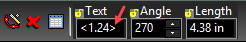
If you select a circle, a diameter dimension will be created.
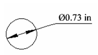
In the Inspector Bar, you can change the text, set the angle of the dimension, and set the length of the leader line.
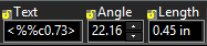
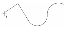
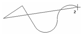
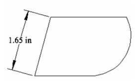
If you select a line or line segment, its length dimension will be created.
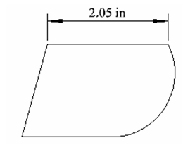
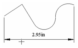
If the line segment is not orthogonal, there are three possible dimensions you can create: Parallel
Orthogonal (vertical)
Orthogonal (horizontal)
If you select an arc or arc segment, a radial dimension will be created.
To create an angular dimension, press Shift and select the two lines.
Smart dimensions also work for linear and circular edges of solid ACIS objects. You can use this feature to dimension cross-section generated through the Drafting Palette, as long and the Surface Engine option in the Drafting Palette was turned off when the section was created.
Linear and angular dimensions can also be created for 3D Polylines.
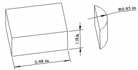
Surveyor Dimensions
Linear and Angular dimensions can be displayed in surveyor format.
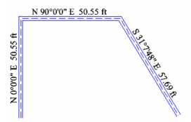
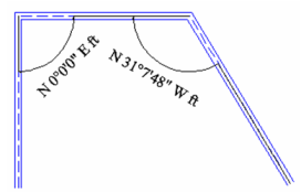
For linear dimensions, surveyor format is angle (degree-minutes-seconds) and length. For angles, surveyor format is degree-minutes-seconds.
Before creating surveyor dimensions, open the Properties for any dimension tool. On the Units / Tolerance page, set the Format to Surveyor.
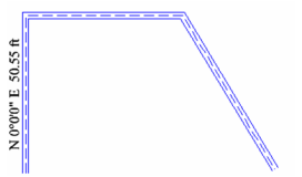
 In this example, surveyor dimensions will be placed using Parallel Dimensions, on three segments of this Multi Line Polyline.
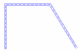
- After setting Surveyor in the dimension tools' Properties, activate the dimension tool you want to use (in this case, Parallel, but you can use any linear dimension). Click the segment you want to dimension. (Only segment dimensioning is available when creating surveyor dimensions; you cannot click two points.) The red arrow indicates the direction in which the segment is measured.
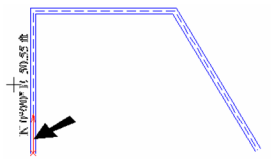
- If you want the segment measured from the other side, select Invert from the Inspector Bar or local menu.

- Click a second time to place the dimension.
- Dimension additional segments the same way.
You can dimension an angle using surveyor dimensions as well.
MultiLeader Dimensions
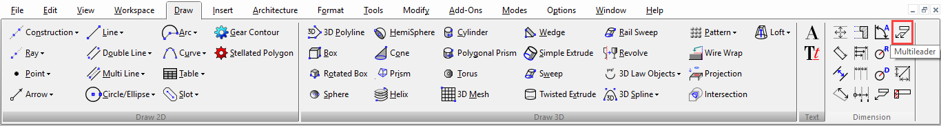
Default UI Menu: Dimension / MultiLeader
Ribbon UI Menu:
 MultiLeader dimension are a special category of dimension tool designed to support entities imported from external DWG files. These leaders attached a single piece of content to multiple leader arrows. the content may be text, a block, or nothing. The content and structure of multileaders is defined by the MultiLeader style.
Local menu option:
Arrowhead First: The first click places an arrowhead. Turning this option on turns off Content First
Content First: The first click places the content. Turning this option on turns of Arrowhead first
Fixed Leader Points: Limit the number of points within each leader to the number specified in the style. The default is 2, one at the arrowwhead and one at the content. Once both points have been placed, a new leader will begin for the current multileader. If this option is off leaders may have as many points as you wish.
Insert Next Leader: This option is only available if Fixed Leader Points is turned off. When available the option finishes the current leader at its last selected point and begins the next leader.
Finish: Finishes the entry for all of the leaders.
MultiLeader dimension are a special category of dimension tool designed to support entities imported from external DWG files. These leaders attached a single piece of content to multiple leader arrows. the content may be text, a block, or nothing. The content and structure of multileaders is defined by the MultiLeader style.
Local menu option:
Arrowhead First: The first click places an arrowhead. Turning this option on turns off Content First
Content First: The first click places the content. Turning this option on turns of Arrowhead first
Fixed Leader Points: Limit the number of points within each leader to the number specified in the style. The default is 2, one at the arrowwhead and one at the content. Once both points have been placed, a new leader will begin for the current multileader. If this option is off leaders may have as many points as you wish.
Insert Next Leader: This option is only available if Fixed Leader Points is turned off. When available the option finishes the current leader at its last selected point and begins the next leader.
Finish: Finishes the entry for all of the leaders.
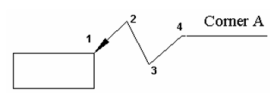
- Select the MultiLeader tool.
- Click to select the first point for the leader.If the Content First option is selected this will be the location of the content, otherwise it will be the location of the first arrowhead.
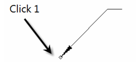
- Click to select the second point for the leader.If the Content First option is selected this will be the location of the first arrow head, otherwise it will be the location of the first content.
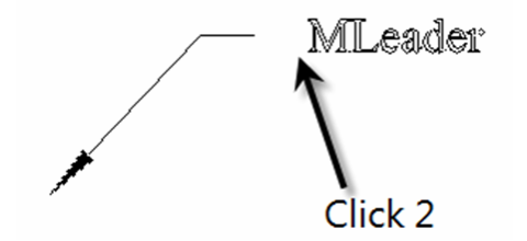
- If the default settings and style is in use a new leader will begin after the second click.
- Click to set the arrow head of the next leader.The content position is already set. So with the standard limit of two points per leader selecting each point sets the current leader then begins the next.
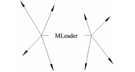
- If you have Fixed Leader Points turned off, continue entering points as needed then use Insert Next Leader to move on to the next leader in the sequence.
- Click Finish when you are done creating leaders.
Using the Edit tool you can add and subtract leaders on existing multileaders. you can also add, subtract, and move nodes of multileaders.
MultiLeader Properties
MultiLeader have different properties than standard dimensions.
MultiLeader Format
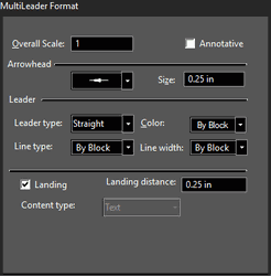 Overall Scale: Sets the overall scale for the multileader.
Annotative: Set whether the multileader is annotative or not. This has no effect within the application is strictly a setting to support external DWG applications.
Arrowhead: Sets the type of arrowhead used in the multileader.
Size: Sets the size of the leader arrowheads.
Leader Type: Sets whether the type is a line, spline, or none.
Color: Sets the color for the leaders.
Line Type: Sets the line type for the leaders.
Line Width: Sets the line width for the leaders.
Landing: Sets whether there will be a landing, a horizontal line attaching the end of leaders to the content.
Landing Distance: Sets the landing width.
Content Type: This is controlled by the Style
Overall Scale: Sets the overall scale for the multileader.
Annotative: Set whether the multileader is annotative or not. This has no effect within the application is strictly a setting to support external DWG applications.
Arrowhead: Sets the type of arrowhead used in the multileader.
Size: Sets the size of the leader arrowheads.
Leader Type: Sets whether the type is a line, spline, or none.
Color: Sets the color for the leaders.
Line Type: Sets the line type for the leaders.
Line Width: Sets the line width for the leaders.
Landing: Sets whether there will be a landing, a horizontal line attaching the end of leaders to the content.
Landing Distance: Sets the landing width.
Content Type: This is controlled by the Style
MultiLeader Content
The feature of the MultiLeader Properties Content page vary depending upon the content type specified in the selected MultiLeader Style. If the Content Type in the style is set to none the page will be blank. If the Content Type is set to text the page will be as follows: 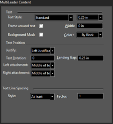 Text Style: Set which Text style from the Style manager is used in the multileader.
Height: Sets the height of the text. This will override the settings in the styles.
Frame around text: specifies whether a box will be drawn around the text of the multileader.
Width: Sets the width of the paragraph.
Background Mask: Creates a mask for objects behind the text.
Color: Sets the text color.
Justify: Specifies the text justification.
Left Attachment: Specifies the vertical position where the leaders on the left side of the content.
Right Attachment: Specifies the vertical position where the leaders on the right side of the content.
Text Rotation: Specifies the angle of the content text.
Landing Gap: Specifies the distance between the end of the landing and the content.
Style: Select At Least to automatically set the line size relative to the largest character of a line. Select Exactly to keep all lines the same size.
Factor: Sets the distance between lines. If the Content Type in the style is set to block the Content page will look as follows:
Text Style: Set which Text style from the Style manager is used in the multileader.
Height: Sets the height of the text. This will override the settings in the styles.
Frame around text: specifies whether a box will be drawn around the text of the multileader.
Width: Sets the width of the paragraph.
Background Mask: Creates a mask for objects behind the text.
Color: Sets the text color.
Justify: Specifies the text justification.
Left Attachment: Specifies the vertical position where the leaders on the left side of the content.
Right Attachment: Specifies the vertical position where the leaders on the right side of the content.
Text Rotation: Specifies the angle of the content text.
Landing Gap: Specifies the distance between the end of the landing and the content.
Style: Select At Least to automatically set the line size relative to the largest character of a line. Select Exactly to keep all lines the same size.
Factor: Sets the distance between lines. If the Content Type in the style is set to block the Content page will look as follows: 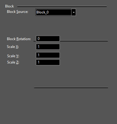 Block Source: Specifies the block to be used in the content.
Block Attachment: Specifies whether the block will be attached to the multileader using its geometric center of the block, or attached using the block reference point (insertion point).
Block Color: Sets the block color.
Block Rotation: specifies the angle for the rotation of the block insertion.
Scale X: Sets a scaling factor for the block along its X axis.
Scale Y: Sets a scaling factor for the block along its Y axis.
Scale Z: Sets a scaling factor for the block along its Z axis.
Block Source: Specifies the block to be used in the content.
Block Attachment: Specifies whether the block will be attached to the multileader using its geometric center of the block, or attached using the block reference point (insertion point).
Block Color: Sets the block color.
Block Rotation: specifies the angle for the rotation of the block insertion.
Scale X: Sets a scaling factor for the block along its X axis.
Scale Y: Sets a scaling factor for the block along its Y axis.
Scale Z: Sets a scaling factor for the block along its Z axis.
MultiLeader Styles
You can manage and create MultiLeader styles using the Style manager. For more on the Style Manager see . In the Style Manager, there is one style, "Standard," listed under "MultiLeader styles".
Note: In the Preview area, you can click to zoom part of the graphic. Double-click to fit the graphic in the window.
- You can change the "Standard" style, but if you want to preserve this style, make sure "Standard" is highlighted, then click Create New.
- Assign a name or accept the default.
This creates a new which is a copy of "Standard."
3. To change the current multileader to the new style, open its Properties to the General page.
Dimension Formatting Codes
You can insert formatting codes and text into Dimension to control the information that is displayed.
| Codes | Definition | Example |
|---|---|---|
| <…> | The automatic Dimension text | |
| \L...\l | Turns underline onand off | IMSI \LTurboCAD\l |
| \~ | Inserts a nonbreakingspace | IMSI TurboCAD\~LTE |
| \ | Inserts a backslash | IMSI \TurboCAD |
| {...} | Inserts an opening and closing brace | IMSI {TurboCAD} |
| \Cvalue; | Changes to thespecified color | IMSI \C2;TurboCAD |
| \Hvalue; | Changes to the textheight specified indrawing units | IMSI \H2;TurboCAD |
| \Hvaluex; | Changes the text heightto a multiple of thecurrent text height | IMSI \H3x;TurboCAD |
| \S...^...; | Stacks the subsequent text at the /, #, or ^ symbol | 1.000\S+0.010^-0.000; |
| \Qangle; | Changes obliquing angle | \Q20;IMSI |
| \Wvalue; | Changes width factor to produce wide text | \W2;IMSI |
| \A | Sets the alignment value; valid values: 0, 1, 2(bottom, center, top) | {\A0; 1}{\A1; 2}{\A2; 3} \SX+A/Y |
| \P | Ends paragraph | IMSI\PTurboCAD |
| \X | Creates a paragraph break. | IMSI \X <...> |
| %%u | Toggles underscoring on and off. | %%uTurboCAD |
| %%d | Draws degrees symbol (°). | %%dTurboCAD |
| %%p | Draws plus/minus tolerance symbol (±). | %%pTurboCAD |
| %%c | Draws circle diameter dimensioning symbol . | %%cTurboCAD |
| %%% | Draws a single percent sign (%). | %%%140 |
| %%nnn | Draws character number nnn.NOTE: nnn will only work with ASCII values. If youwish to use Unicode characters of look up anASCII value. Use the Character Map Utility. |
These codes can be inserted in a dimensions Attribute field, and Info fields.
You can also insert codes into the Prefix or Suffix fields, but these are limited to only a few characters.
