Components of the UI
The main area of the TurboCAD screen is the drawing area. When creating and inserting 2D and 3D objects, you typically work in Model Space, and when putting your model on paper, Paper Space is used. By default, the background color is white, but you can change that by selecting Options / Background Color and choosing another color. Nearly all components of the screen can be customized.
Coordinate Fields
When creating or sizing objects, you can define points by entering them directly into the Coordinate Fields. By default, this toolbar is located at the lower right corner of the screen.
 When moving the cursor, the values in the fields update dynamically. The type of coordinates depends on the coordinate system you are using. In the absolute and relative coordinate systems you use X, Y coordinates. In the polar coordinate system you enter an angle and distance.
You can access the numeric fields via the cursor, or by pressing Shift+Tab or Ctrl+R. You can also press Tab to scroll between Coordinate fields.
When moving the cursor, the values in the fields update dynamically. The type of coordinates depends on the coordinate system you are using. In the absolute and relative coordinate systems you use X, Y coordinates. In the polar coordinate system you enter an angle and distance.
You can access the numeric fields via the cursor, or by pressing Shift+Tab or Ctrl+R. You can also press Tab to scroll between Coordinate fields.
Tip: If you want to jump from the Inspector Bar to the Coordinate Fields, first press Esc, then Ctrl+R.
If you enter a value and press Enter, Any Ortho or snap modes are ignored. You can also enter the results of mathematical expressions from the Calculator.
Locking: You can lock a coordinate by clicking the lock box. This means that no matter where you place the cursor, the value will remain fixed.
 You can also lock coordinates by using the Lock options in the Modes menu.
Tip: The Coordinate Field locks are particularly useful when you lock just one field. If you use a locked value in one field, you can then set the second coordinate using the mouse. This makes it easy to define a series of points along a specific horizontal or vertical line.
The Coordinate Field also provides access to snap modes. Disable the SNAP button to temporarily turn off any running snaps, and disable the GEO button to temporarily turn off any running geometric aids Right-clicking on either the SNAP or GEO fields opens the Drawing Aids window.

Drawing Area - Model Space and Paper Space
For creating and laying out your drawing, TurboCAD provides you with two drawing environments: Model Space and Paper Space. Model Space is the environment in which you create your drawing, usually called a model. In this area you do drafting and design work, creating two-dimensional drawings or three-dimensional models. Paper Space is the environment in which you create the final layout of your drawing for printing or plotting it on paper. In Paper Space you usually arrange the drawing's elements on a sheet of paper.
Note: Floating Model Space enables you to use Model Space tools within a viewport in Paper Space.
You can use the small button at the top left corner, at the intersection of the rulers, to toggle between Model and Paper Spaces.
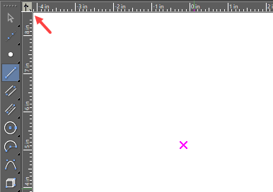
Note: If the rulers are turned off, this button will not appear. Go to Program Setup/Desktop to toggle the ruler display.
There are also workspace tabs at the lower left corner of the screen. By default, each file starts with one tab for Paper Space. Click the tabs to switch spaces.
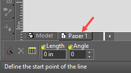
Note: If scroll bars are turned off, these tabs will not appear. Go to Program Setup/Desktop to toggle the scroll bar display.
Inspector Bar
Enables you to create objects by defining some or all of its numerical parameters. By default, the Inspector Bar is located immediately below the drawing window.
Note: You can customize the Inspector Bar appearance, by choosing Classic or Custom in the Desktop page of the Program Setup. You can also display or hide the Inspector Bar on this page.
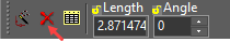
For most tools, the Inspector Bar is divided into three parts. On the left side are three icons, Auto Add Constraints, Cancel and Properties.
Auto Add Constraints: When enabled, it automatically applies constraints while drawing objects.
Cancel: Ends an operation without completing it. For some tools, once the operation is complete the tool remains active. You must click Cancel, or activate another tools, to exit the tool. The hotkey for Cancel is the Esc key or space bar.
Properties: Opens the Properties window for the object you are creating.
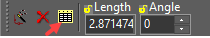
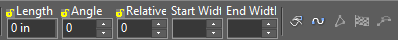
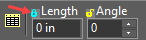
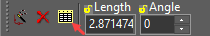 The middle section of the Inspector Bar contains the numeric fields. For example, when creating a line segment in the Polyline tool, you can set the Length, Angle, and Start and End Widths. For a circle, the fields would be Radius, Diameter and Circumference. When moving the cursor to position or size an object, the values in the fields update dynamically.
 You can access the numeric fields via the cursor, or by pressing Tab or Ctrl+E. You can also press Tab to scroll forward to the next field. Return to the drawing by pressing Esc or clicking in the drawing.
Tip: If you want to jump from the Coordinate Fields to the Inspector Bar, first press Esc, then Ctrl+E.
If you enter a value and press Enter, Any Ortho or snap modes are ignored. You can also enter the results of mathematic expressions from the Calculator.
Locking: For some fields you can lock their values by clicking the lock symbol. This means that no matter where you place the cursor, the value will remain fixed.
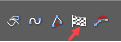
 The right side of the Inspector Bar contains options relevant for the tool or mode.
Note: All options on this section of the Inspector Bar can also be accessed from the local menu, opened by right-clicking.
There are two common local menu options that appear for many functions: Finish and One Step Back. Finish: Completes the operation and exits the tool. For instance, when creating a polyline, you can click Finish after creating the last segment. The hotkey for Finish is Alt+F.
Note: For many tools, double-clicking when creating the last component of an object is equivalent to clicking Finish.
One Step Back: For tools that require multiple steps, this enables you to scroll backward through the steps already completed until you reach the desired start point, then continue working.
 When in Select Edit mode, the Inspector Bar has a different appearance. The numeric fields enable you to change the size, scale, and rotation of the selected objects, while the local menu options include Make Copy, Selector properties, etc. Size and Position fields for 3D objects are turned off by default.

Note: The options that appear on the Inspector Bar in Select Edit mode depend on whether you are in 2D or 3D Selector mode, and can be changed.
Customizing the Inspector Bar
You can remove any of the fields or local menu option icons by right-clicking anywhere on the Inspector Bar (except the numeric fields). This opens customize dialogue which lets you add or delete any of the controls. You can select icon from inspector bar and drag it away to exclude from inspector bar and you can add commands by searching them in commands tab and selecting it and draging into the inspector bar. You can also change the width of any of the numeric fields by dragging either side with the mouse.
Local Menu
The local menu, sometimes called the context menu, popup menu or context-sensitive menu, is opened by right-clicking the mouse. The contents of this menu differ depending on where you right-click, and in which tool you are working.
Note: You can customize the contents of the local menu via Tools / Customize.
When working in a tool, options on the local menu also appear in the Inspector Bar. In addition to customizing local menu items, you can add popup toolbars - icons that will appear each time you open the local menu.
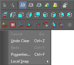 The following items are found on most local menus:
Cancel: Cancels the current operation, and exits without completing.
Undo: Undoes the last operation and return to the previous condition. The last operation is displayed here.
Redo: Reverses Undo.
Properties: Opens the Properties window.
Local Snap: Sets the snap mode for the next point only.
The following items are found on most local menus:
Cancel: Cancels the current operation, and exits without completing.
Undo: Undoes the last operation and return to the previous condition. The last operation is displayed here.
Redo: Reverses Undo.
Properties: Opens the Properties window.
Local Snap: Sets the snap mode for the next point only.
Menu Bar
The menu bar is at the top of the screen. (Most tools are available in toolbar icons as well).

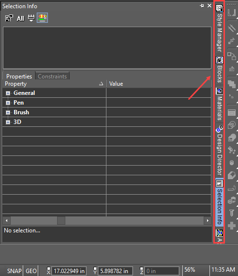
Palette Area
By default the palette area is on the right side of the workspace.
 For details on each palette,
Rulers
You can work with rulers to have a visual representation of the current dimensions.
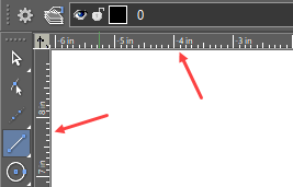 Rulers are only displayed for orthographic views (top, left, right, etc.) and display the current Model Space or Paper Space units.
Tip: Another handy visual aid, which can be used in tandem with rulers, is the grid.
Scroll Bars
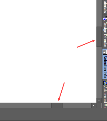 Your drawing can be larger (much larger!) than what you see on the screen. The scroll bars can be used to pan to a different area of your drawing. Click on the arrows at the ends of the scroll bars to move a small amount. Drag the scroll box itself to move faster.
Status Bar
Located at the lower left corner of the screen, the Status Bar lets you know the current status of the model.
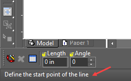 For example, if you have just activated the Line tool, the Status Bar will contain the prompt "Define the start point of the line."
Toolbars
Toolbars are groups of related icons. They can be located on top and below the screen, and to either side of the screen.
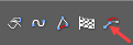
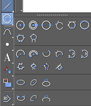
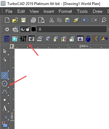 By default, the Standard toolbar appears at the top of the screen, and the Property toolbar appears just below it. Drawing tools appear along the left side. Icons that have a small yellow or black triangle in the corner are fly-outs. If you click one and hold the mouse button...
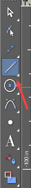
... the entire toolbar will "fly out," and you can select the desired icon. The color of the triangle is dependant upon UI settings.
You can also create tabbed toolbars and popup toolbars that appear when you open the local menu. You can modify a toolbar's icons and create your own toolbars. In addition to the default toolbars you see when you first start TurboCAD, there are numerous other toolbars you can display. There are two ways to access additional toolbars: Open the Toolbars and Menus page of Program Setup. This opens the Toolbars tab of the Customize window, which contains a list of all available toolbars; check the ones you want to see. Right-click in any toolbar area. The local menu that appears contains the list of all available toolbars; select a toolbar to add or remove from the screen.
Moving, Docking, and Rolling Toolbars
By default, certain toolbars are docked along the sides of the screen, and when you display another toolbar it appears "floating" on the screen. You can dock and undock all toolbars, and the same applies for palettes as well.
You can drag a toolbar by picking it on its top or bottom edge (for vertical toolbars) or either side edge (for horizontal toolbars).
 For palettes, pick and drag it by its title bar.
Moving a toolbar to any edge of the screen will dock it to that edge. Docking to either side creates a vertical toolbar, docking to the top or bottom of the screen creates a horizontal toolbar. You can also move a toolbar onto the drawing area, where it will "float" on the screen.
For palettes, pick and drag it by its title bar.
Moving a toolbar to any edge of the screen will dock it to that edge. Docking to either side creates a vertical toolbar, docking to the top or bottom of the screen creates a horizontal toolbar. You can also move a toolbar onto the drawing area, where it will "float" on the screen.
Tip: You can also undock or dock a toolbar by double-clicking any icon on the toolbar.