Edit Tool

(Available in all TurboCAD Variants)
Default UI Menu: Edit/Edit Tool
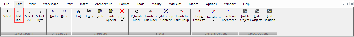
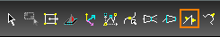
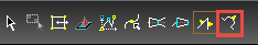
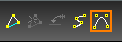
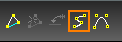
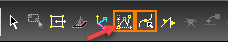
Ribbon UI Menu:
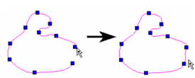
Nodes are hidden markers identifying elements of geometric objects. The Edit Tool enables you to reshape objects by editing their nodes. You can edit a single node or multiple nodes - even a group of nodes belonging to different objects.
Note: This section focuses on editing nodes of 2D objects. For 3D objects,. For editing tables, . And for editing walls,
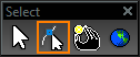
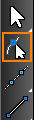
There are several ways to activate the Edit Tool: Click Edit Tool on the Select toolbar, then select the object to edit.
 Selectdit Tool, then select the object to edit. Select the object that you wish to edit, then select Edit Tool from the local menu. You can also click the icon on the Inspector Bar.
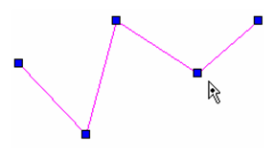
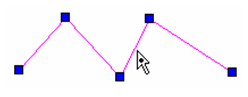
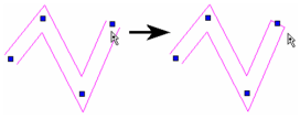
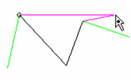
 Select the object to edit, then press Ctrl and select it again. Access theEdit Tool from the Selection Info Palette. . In Edit Tool mode, the cursor becomes an arrow with a dot.

When the node editing is finished, you can return to Select Edit mode by selecting it from the local menu, by clicking the icon on the Inspector Bar, or by pressing Esc.
 You can then exit Select mode by clicking outside the selection set, or by pressing Esc again.
Note: If you need to node edit an object that is part of a group, explode the group first (Modify / Explode). For an object that is part of a block, you can node edit the object in Edit Content mode.
Adding a Node
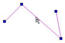
Adds nodes to lines and line segments, including objects created using double lines and multi-lines. You can also add nodes to Bezier curves, splines, and sketches.
- Use the Edit Tool on the object to which you want to add a node.
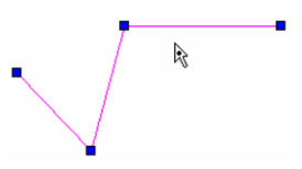
- Press Ctrl while placing the cursor where you want to add the node. The cursor has a + symbol.
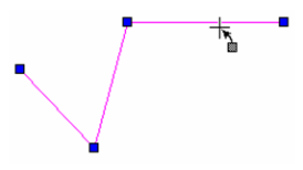
- Click to add the node.
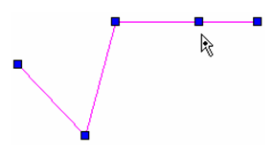
(You could also place the cursor where you want to add the node, then select Add Node from the local menu.)
- You can now drag the new node to create a new line segment.
The same method can be used to add nodes to curves.
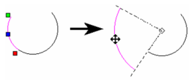
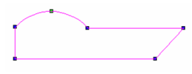
Insert Arc
The Insert Arc function of the Edit Tool allows you to insert an arc at the location of most nodes of a polyline.
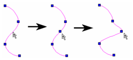
- Start the Edit Tool, then hover over a node.
- Right-click to open the Local menu, and select Insert Arc.
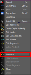
- The arc is inserted.
- The radius of the resulting arc is defined by the Radius field of the Inspector bar.
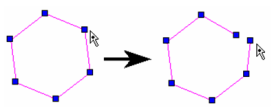
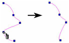
Breaking (Opening) Closed Objects
Breaks a closed object (polygon, closed polyline, rectangle, closed curve, etc.), turning it into a polyline.
- Use the Edit Tool on the closed object you want to break.
- Right-click on the node at which you want the break, and select Break from the local menu.
- The object is now an open polyline, with two end nodes at the node where you broke the object.
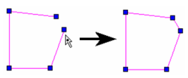
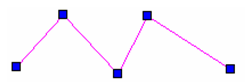
Closing Open Objects
Closes an open object (polyline, open curve), turning it into a closed polyline, curve, or polygon.
- Use the Edit Tool on the open object you want to close.
- Right-click on the node at which you want to close the object, and select Close from the local menu.
- A line segment is created between the node you selected and the other endpoint.
Note: If the two endpoints of the polyline share the same location, the object will simply be closed geometrically. If you simply snap the endpoints of a polyline together, the resulting object will only appear to be closed but is still considered open. This means, for example, that the object cannot be filled with a hatch pattern. In order to geometrically close the object, you must use this feature.
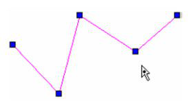
Deleting Nodes
Deletes nodes from lines and line segments, including objects created with double lines and multi-lines. You can also delete nodes from Bezier curves, splines, and sketches. You cannot delete a node that is needed to define an object as a line segment or polygon. This means that you cannot delete the endpoint of a single line segment, and you cannot delete any node of a triangle. If you delete the endpoint of a polyline, you will delete the entire line segment that terminates at that point.
- To delete a single node, use the Edit Tool on the object from which you want to delete a node.
- Press Ctrl while placing the cursor where you want to delete the node. The cursor becomes a "trash can" symbol.
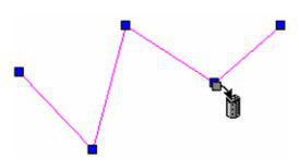
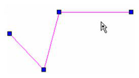
- Click to delete the node. The adjacent nodes will be connected to form a new segment.
You can also use the local menu to delete one or more nodes. Within the Edit Tool, drag a selection window around the node or nodes you want to delete. Selected nodes turn from blue to magenta. Then select Delete Node(s) from the local menu.
Note: If you remove a node from a polygon, the polygon will remain closed, but will become an irregular polygon.
You can also delete nodes from Bezier curves, splines, and sketches.
Editing Circles, Ellipses, and Arcs
In addition to adding, deleting, or moving nodes, there are several Edit Tool features unique to circular and elliptical objects.
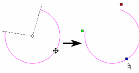
Changing the Radius of a Circle or Arc
- Use the Edit Tool on the circle or arc whose radius you want to change.
- Click and move the blue handle to resize the object. You can also enter the new radius in the Inspector Bar.
Changing the Axes of an Ellipse or Elliptical Arc
- Use the Edit Tool on the ellipse or elliptical arc whose axes you want to change.
- There are two blue handles, one for the major axis and one for the minor.
- Click and move the relevant blue handle to resize the axis. You can also enter the new axis length in the Inspector Bar.
To scale the object while maintaining its aspect ratio (major axis to minor axis), hold the Shift key while dragging either blue handle.
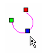
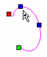
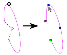
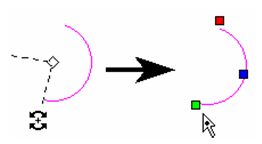
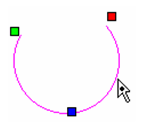
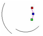
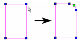
Changing Start and End Angles
- Use the Edit Tool on the object whose start and end angles you want to change.
- The green handle is used to change the start angle, and the red handle is for the end angle.
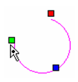
- Click and move either angle handle to resize the angles. You can also enter the new angles in the Inspector Bar.
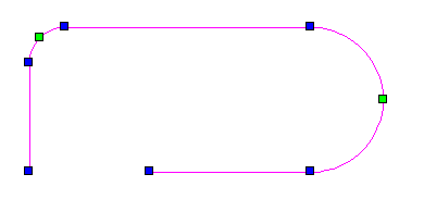
Dividing an Arc
Adds nodes to an arc or circle, breaking it into separate arcs. The resulting arcs can be edited just like an arc.
- Use the Edit Tool on the arc or circle you want to divide.
- Right-click over the arc you want to divide, and select Arc Divide from the local menu. Enter the number of arcs in the inspector bar.
The arc is divided into the specified number of arcs. Each resultant arc can be node edited separately.
To node edit, a different arc, simply click on it while still in the Edit Tool.
Tip: To divide an arc segment that is part of a polyline, right-click on the green node and select Insert Arc. This divides the arc into two equal segments.
Editing Dimensions
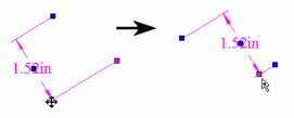
For details on creating dimensions, When using theEdit Tool on a dimension, there are several nodes for editing: one at each extension line, one on the dimension line itself, and one on the text. Each can be moved to change the dimension.
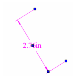
Move the node on an extension line to change its length and/or position. If this change leads to a new dimension value, the new value will appear after the node is moved.
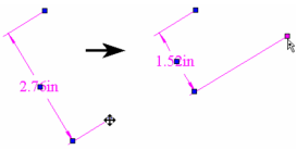
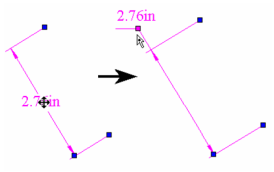
Move the node on the dimension line to change the position of the dimension text.
Move the node on the dimension text to move the text. How the text is moved depends on the Text Movement option set on the Format page of the dimension's Properties Keep Dimension Line with Text: The dimension line will move with the text.
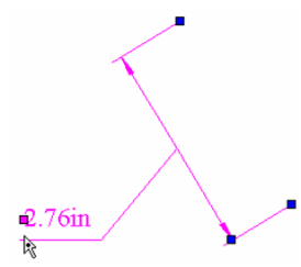
Move Text, Add Leader: The moved dimension text will be attached to the existing dimension line by a leader.
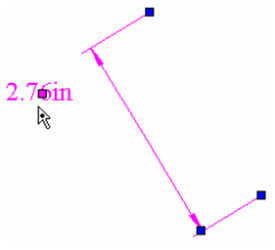
Move Text, No Leader: Only the dimension text will move.
Editing Linear Objects
In addition to adding, deleting, or moving nodes, there are several Edit Tool features unique to linear objects.
Dividing a Line Segment
Adds nodes to a line or line segment, breaking it into a polyline composed of segments of equal length. Double lines and multi-lines can also be divided.
- Use the Edit Tool on the object you want to divide.
- Right-click over the segment you want to divide, and select Divide Segment from the local menu. Enter the number of segments in the inspector bar. The selected segment is divided into the specified number of segments.
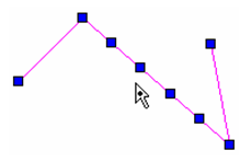
- You can now drag any of the new nodes to create new line segments.
Hiding or Showing a Line Segment
Applies only to single-line segments.
- Use the Edit Tool on the object whose segment you want to hide.
- Right-click over the segment you want to hide, and select Hide Segment from the local menu. The segment is no longer displayed.
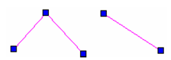
- To show the segment again, select Show Segment from the local menu.
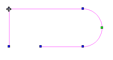
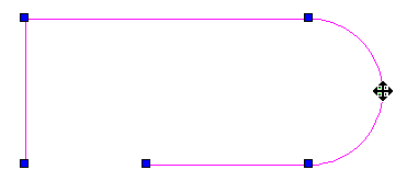
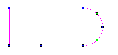
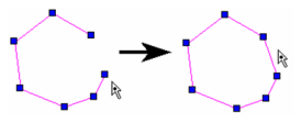
Filleting Two Line Segments
Adds an arc connecting two line segments, creating a fillet.
- Use the Edit Tool on the multi-segmented object you want to fillet (polyline, rectangle, polygon, etc.).
- Enter the fillet radius in the Inspector Bar.
- Right-click on the node to fillet and select Insert Arc.
Modifying Line Widths
- Use the Edit Tool on the line object (line, rectangle, polygon, etc.) whose width you want to change. Arc segments of polylines can be edited as well.
2. Right-click and select *E. Drag an endpoint to widen it, or enter the width in the Inspector Bar.
With this method, each endpoint will be sized individually, with no relation to any adjacent segments.
To modify the width of all adjacent segments, right-click and select Edit Line Width.
Closing and Opening Endpoints of Double Lines
Creates or removes a start or end cap of a double line. This can also be controlled in the double line's Properties -
- Use the Edit Tool on the double line object whose endpoint you want to close.
2. Right-click on the end node, and select Close Double End.
3. To open the endpoint, select Open Double End.
Modifying Double Line Intersections
Right-click on the intersection node you want to modify. For the options
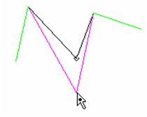
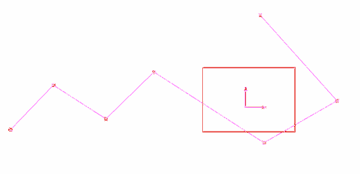
You can use a selection window to edit a group of nodes, even if the nodes belong to different objects.
- Activate the Edit Tool. To select multiple objects use the Shift key. You can use Ctrl+A to select all objects for node editing.
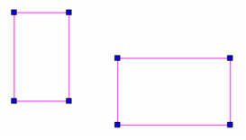
- Use a selection window to enclose all the nodes you want to edit.
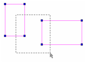
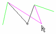
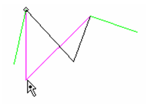
- The selected nodes turn from blue to magenta. When you move any of the selected nodes, all nodes move as a group.
- To deselect nodes, draw an "empty" selection window (one that does not encompass any nodes).
Node Filter
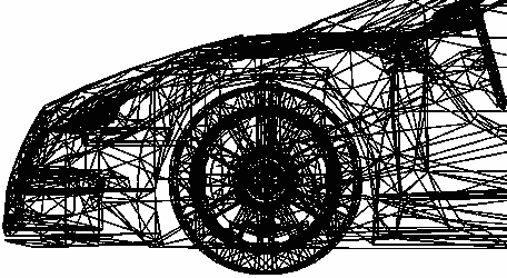
In some circumstances, objects will have so many nodes that indicating and editing them all simultaneously slows down operations considerably.
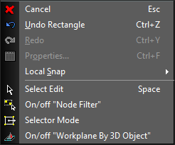
To deal with this there is an option called On/Off "Node Filter" available from the Local menu and Inspector bar.
 Select the Edit tool.
Turn on the Node Filter.
Select the Edit tool.
Turn on the Node Filter.
 Select the object.
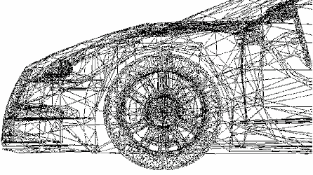 Drag to select the desired nodes.
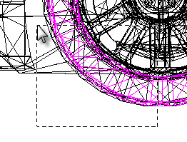 Only those nodes are selected.
 Hold down the SHIFT key to select multiple discrete areas,
 Proceed with editing.
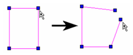
Editing Segments
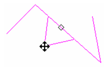
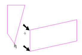
For objects with multiple segments, you can move segments so that they remain parallel to their original location. Arc segments can also be edited.
- Use the Edit Tool on a multi-segmented object like a polyline, rectangle, polygon, etc.
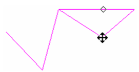
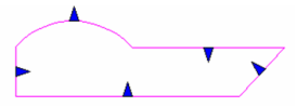
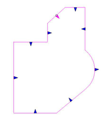
- From the local menu or Inspector Bar, select Edit Segments.
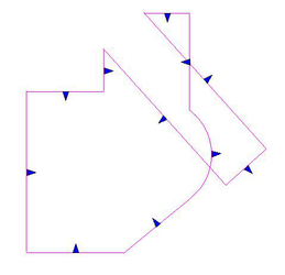
The nodes are no longer marked, and segments are marked with triangles.
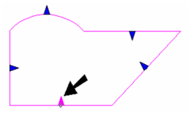
- Click and drag one of the segments. It remains parallel to its original location, and its length updates to meet adjacent segments.
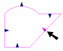
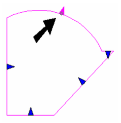
- If you edit an arc segment, its radius will change and its center will remain in place.
Note: This also works for walls, but each wall can be node edited separately when using Edit Segments.
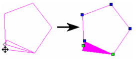
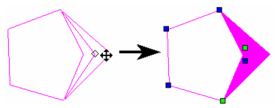
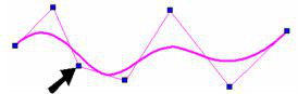
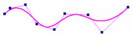
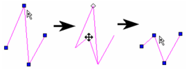
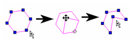
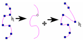
Editing Segments Push Mode
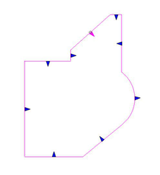
 When Push Mode is off segments are simply moved as you drag an arrow and re-sized as needed.
 However, when Push Mode is on rather than re-sizing, new geometry is created to fill the resultant gaps.
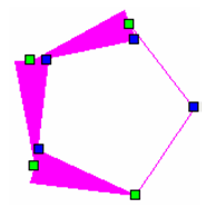
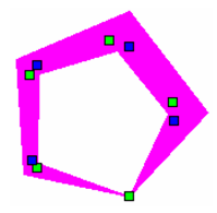
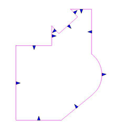 If the object is a standard 2D polyline etc. you can create self-crossing geometry.
 However, you cannot create self crossing geometry if the object is a region. Attempting to do so will generate the following error:
Editing Splines and Bezier Curves
In addition to adding, deleting, or moving nodes, there are several Edit Tool features unique to splines and Bezier curves.
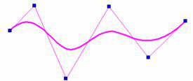
Changing the Shape of a Spline or Bezier Curve
- Use the Edit Tool on the curve you want to edit.
- Click and drag any point along the curve.
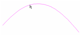
The control points update accordingly.
Changing Control Points and Fit Points
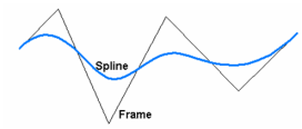
Splines are created by specifying either a series of fit points (points through which the spline passes) or control points (guide points). For either type of spline, you can view and move both types of points. It is easier to understand the types of points when the spline is displayed with its frame. Open the spline's Properties to the Curves page and check Show Frame.
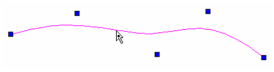
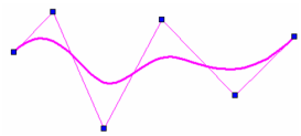
- Use the Edit Tool on the curve you want to edit. By default, Edit Control Points is active in the Inspector Bar and local menu.
- The control points are highlighted at the ends of frame segments. Each point can be clicked and dragged manually or assigned values in the Inspector Bar or Coordinate Fields.
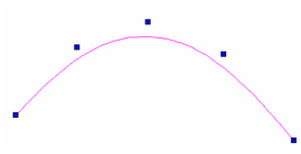
- Switch to Edit Fit Points.
- Now the points through which the spline passes are highlighted. If the spline is open, you can use the green points to change the slope at the spline ends.
Note: Control points and fit points are not available for Bezier curves. For details on node-editing Bezier curves,
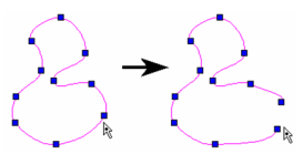
Adding Nodes and Knots
A knot is basically a control point. You can add knots to increase the editing detail of a spline. A node is a point through which the spline will pass (fit point).
- Use the Edit Tool on the spline you want to edit. In this example, the frame of the spline is displayed (check Show Frame on the Curve page of the spline's Properties).
- It does not matter whether fit points or control points are highlighted. To add a control point (knot), right-click on the spline (not on the frame) where you want to add a knot and select Add Knot. The control point is added along the frame.
- If you continue adding knots, you can "tighten" the frame to the spline, providing more control points for editing.
- To add a fit point (node), right-click on the spline, near where it passes through the frame. Select Add Node. The fit point is added along the frame.
- If you continue adding nodes, you can "tighten" the spline to the frame, providing more fit points for editing.
Note: Nodes can be added to Bezier curves as well, but knots can be added only to splines.
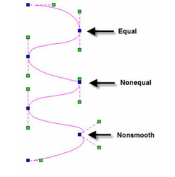
Changing Node Curvature of Beziers
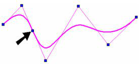
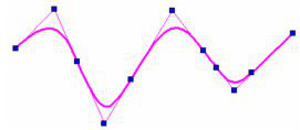
Bezier curve use weighted nodes to control the curvature at each node point.
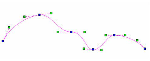
You can control how each node controls the curvature by selecting a node, and right clicking to open the local menu. In the local menu, there are three options for controlling the curvature of a node.
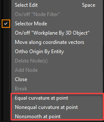
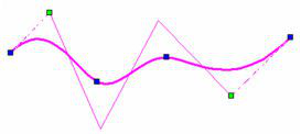
Equal Curvature at point — This is the default. When selected, adjusting one of the green control handles causes the paired handle to change an equal distance, but the handles remain locked to a common control line. This option makes the curve smooth and equal on both sides of the node. Nonequal Curvature at point — When this option is selected, adjusting one of the green control handles does not affect the distance of the paired handle, but the nodes remain locked to a common control line. This option makes the curve smooth but unequal on either side of the node. Nonsmooth at point — When this option is selected, adjusting one of the green control handles does not affect the paired handle at all, the nodes have separate control lines. This option allows you to make a sharp point in the curve.
Note: These controls will have no effect if the "keep Curve Smooth" option is turned off in the curve properties.
The effect of selecting a different curvature only appears after you begin moving an affected handle.
Highlight End Points
You can use the Selection Tool function to highlight the end points of the polyline, polyline 3D, double line/walls, spline/bezier.
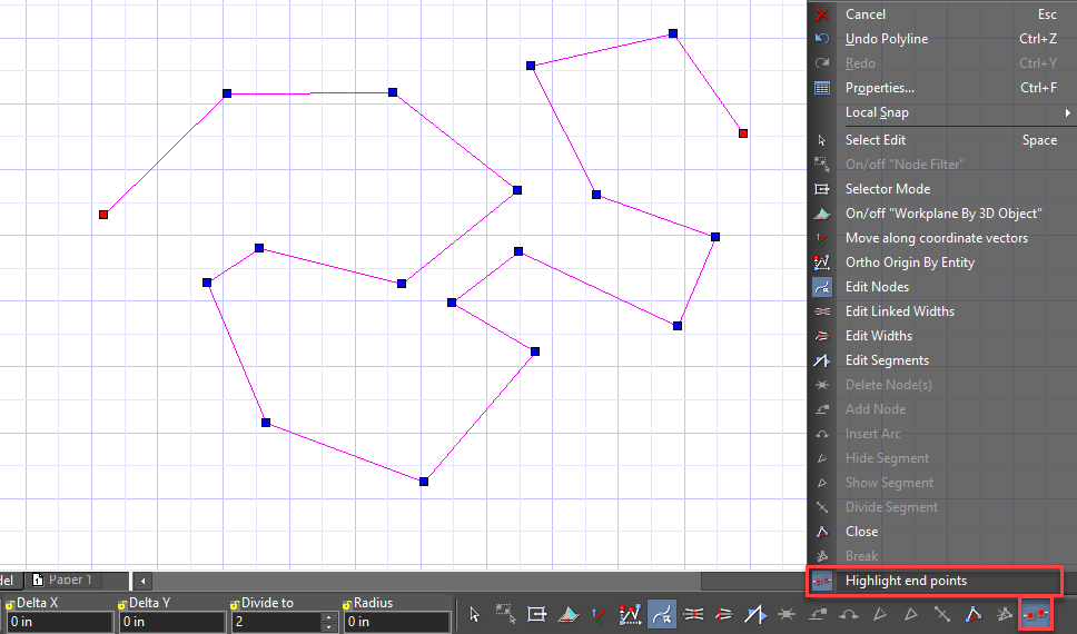
If the “Highlight end points” option is ‘on’, then endpoints marks are red.
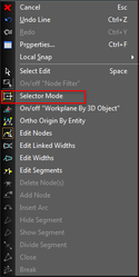
Selector Mode in Edit Tool
You can use the Selection tool functions to edit nodes by turning on the Selection Mode. Selection mode is available from the local menu or from the Inspector bar.
 While in this mode you can select multiple nodes and move them, rotate them, and scale their collective size just as you would any other object using the selector.
Note: The selector type (2D or 3D) that will be used in Edit tool is dependant upon the type that is current for the selector.
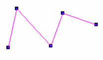
Moving a Node
The most basic method of node editing is to move nodes. Simply click on any node and drag it to its new location.
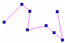
If you want to move nodes orthogonally, you can press Shift while dragging. This example will use a polyline:
In the local menu or Inspector Bar, if Ortho Origin by Entity* is disabled, the nodes will be moved orthogonally according to the active UCS.
 In this mode, you can move the node directly above, below, left, or right of its current position.
If Ortho Origin by Entity is enabled, the node will move so that the segment itself will become orthogonal.
 In this mode, the segment before the node will become either vertical or horizontal.
For Bezier curves, you can choose to have additional control while node editing. By checking Show additional control points in the curve's Properties, you can add two more control nodes at every node. You can also control the tangency at each node.
Node Editing Perpendicular Vectors
It is possible to lock node editing to allow movement only parallel to the standard Perpendicular vectors (x, y, z) by using the local menu item "Move along coordinate vector" This function is available only if one object is selected. If this mode is switched on and some nodes are selected, you can select one of three vectors (x, y, z). and drag it. Note: if the object is 2D then only 2 vectors will be available..
If one of the vectors is selected, then all selected nodes move along the selected vector.
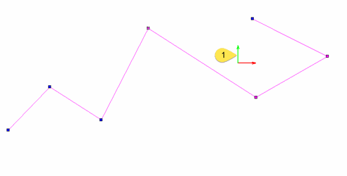
Selector Mode
The Selector mode acts like Selection editing, but applies only to the selected components of the objects rather than the object as a whole.
You can use the Selector Mode within the Edit tool to move selected nodes, edges, and faces.
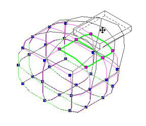
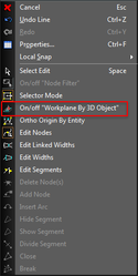
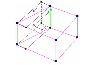
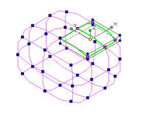
Workplane by 3D Object
 When this option is selected the current workplane (UCS) will automatically switch to the workplane of the selected 3D object.
This allows for easier control under some node editing situations.
When this option is selected the current workplane (UCS) will automatically switch to the workplane of the selected 3D object.
This allows for easier control under some node editing situations.