Using LTE Dynamic Input
 This section covers dynamic dimensions and dynamic input fields.
Dynamic dimensions inform you about the size and location of an object before it is created. These are the same values that appear in the Inspector Bar. You can display one, two, or all available dimensions.
This section covers dynamic dimensions and dynamic input fields.
Dynamic dimensions inform you about the size and location of an object before it is created. These are the same values that appear in the Inspector Bar. You can display one, two, or all available dimensions.
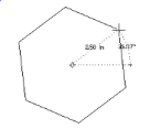 If you choose to display one or two dynamic dimensions, the order of dimensions follows the fields in the Inspector Bar. For example the first field for the Polygon tool is Angle.
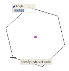 Input fields enable you to enter geometric data in the drawing window, instead of the Inspector Bar. In this example, Input fields are displayed next to the cursor, and dynamic dimensions are turned off.
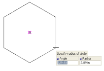 If you don't want the input fields to follow the cursor, you can choose to place them at the bottom of the drawing window.Input fields and dynamic dimensions can work in tandem. If both are displayed, and you choose to place input fields on the dynamic dimensions, you will see input fields in place of the dimension itself.
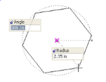 Any input field that does not have a corresponding dynamic dimension, like the Sides field above, will be placed near the cursor, or at the bottom of the drawing window, depending on the option you select.The Customize window also has options for controlling the transparency, width, and title bar display of the input fields.To use the input fields, you can place your cursor in them. Or you can press Tab to enter the first field, then press Tab to jump from field to field.
Tip: If you enter a command alias in an input field, it is the same as entering the alias in the Command Line.