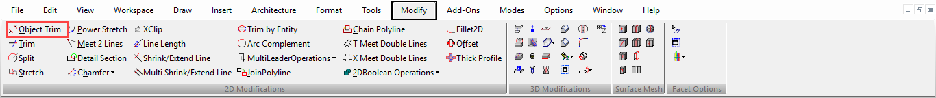
Modifying Geometry
(Available in all TurboCAD Variants)
The Modify tools are generally used to change the shapes of existing objects. These tools do not change physical properties such as layers or line widths; rather they modify the actual geometry.
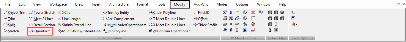
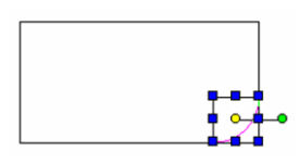
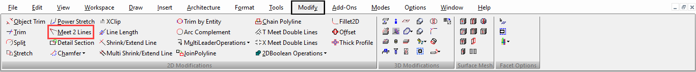
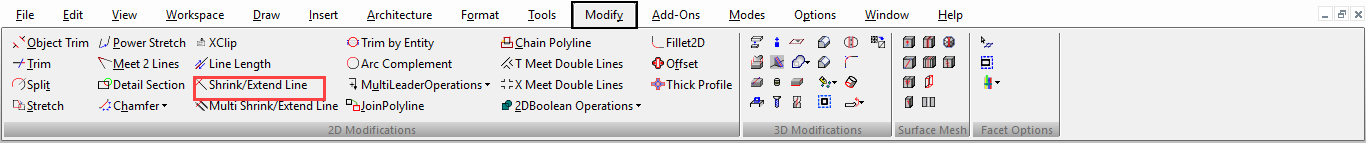
You can display the Modify toolbar by right-clicking in any toolbar area and selecting Modify.
 Some Modify tools require input of two or more objects. If you are working in 3D, all 2D objects selected for modification must lie on the same workplane . To change an object's workplane
(Available in all TurboCAD Variants)
Default UI Menu: Modify/Arc Complement
Ribbon UI Menu:
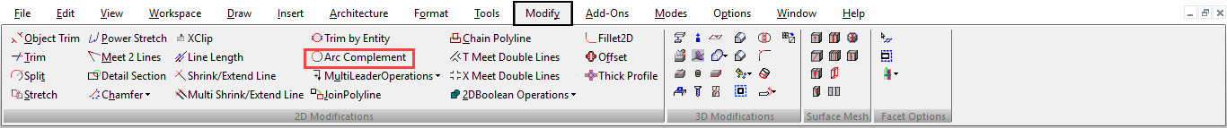
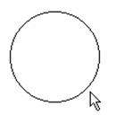
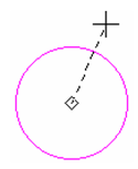
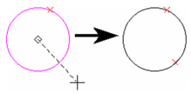
Reverses the start and end angles of an arc. In other words, the arc will become the portion of the original circle that was cut.
- Select the arc you want to modify.
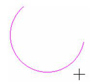
- Click anywhere to create the arc complement.
Tip: When using this tool on arcs that are the result of exploding a polyline, or created as the result of using the Arc Divide option of the Edit Tool, this tool may select more than one arc at a time. If this happens, move the arcs from each other.
Chain Polyline

(Available in Platinum, Professional and Deluxe)
Default UI Menu: Modify/Chain Polyline
Ribbon UI Menu:
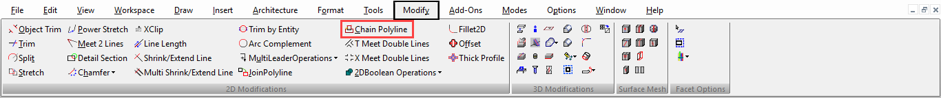
Connects intersecting objects or portions of objects into a single polyline. A chain of connected objects is created, starting from a selected object and proceeding in a specified direction.
Note: The difference between this tool and the Auto Joining option of Join Polyline is that Chain Polyline enables you to create a partial chain, and to work with overlapping objects.
- Select the object from which the chain will start.
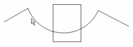
- Set the direction in which the chain will proceed.
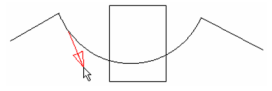
- If overlaps are encountered, you must specify the path to continue the chain.
- The chain proceeds until it reaches the last object, and the polyline is created.
If you do not want the chain to proceed all the way to the last object, you can select Finish from the local menu or Inspector Bar at any time.
Note: The original objects remain in the drawing.
Chamfer
(Available in all TurboCAD Variants)
Default UI Menu: Modify/Chamfer
Ribbon UI Menu:
Connects two lines (single or double lines) with a beveled corner. The selected objects do not have to intersect, and they can overlap.
Note: The resulting objects are separate line segments, unless the Polyline option is used, in which case the result is a polyline.
If the objects overlap, they will be trimmed to create the chamfer. Be sure to select the side of the object you want to remain.
There are three methods for creating chamfers: Distance / Distance, Distance / Angle, and Length / Angle. For all methods, the same local menu options are available.
Local menu options:
Polyline: Chamfers all corners of a polygon or polyline in one step.
- Enter the chamfer distances, angles, or length in the Inspector Bar.
- Select the multi-segmented object you want to chamfer.
- Select Polyline from the local menu or Inspector Bar.

The chamfer is applied to all corners. The resultant object is one polyline.
Warning: Be careful when using the Polyline option with different chamfer distances. The results will not be symmetric.
The other local menu options apply to double lines.
Chamfer Distance - Distance

The chamfer is created by specifying its length along each line.
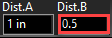
- Enter both chamfer distances in the Inspector Bar. These are the distances along the lines that are to be chamfered. Distance A will be applied to the first line you select.
- Select the first line to chamfer.
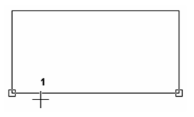
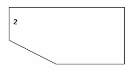
3. Select the adjacent line. The corner is chamfered.
Chamfer Distance - Angle

The chamfer is created by specifying its distance along one line and its angle from the second line.
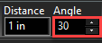
- Enter the distance and angle in the Inspector Bar. The distance is measured along the first line you select.
- Select the first line to chamfer.
3. Select the adjacent line. The corner is chamfered.
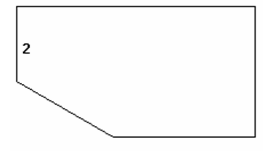
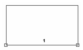
Chamfer Length - Angle
 The chamfer is created by specifying the total chamfer length (as opposed to the distance along the lines) and chamfer angle.
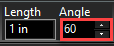
- Enter the length and angle in the Inspector Bar. The length is the total length of the diagonal chamfer line.
2. Select the first line to chamfer.
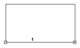
3. Select the adjacent line. The corner is chamfered.
Double Line Options
(Available in all TurboCAD Variants)
You can specify how to create intersections of double lines, and whether cut lines and gaps will occur at the intersections.
For example: if you form a clean T-intersection of two double lines at an angle other than 90 degrees, the end of one of the first line will be cut at an angle, and the second double line will have a gap to accommodate the first double line.
Cleanup: Forms a clean intersection.

If you deselect Cleanup, the first line selected will remain unbroken.
Drop CutLines: Removes the cut lines in the first line, to even out the end of the line.

Drop Gaps: Fills in the gap in the second line.

Fillet

(Available in all TurboCAD Variants)
Default UI Menu: Modify/Fillet 2D
Ribbon UI Menu:
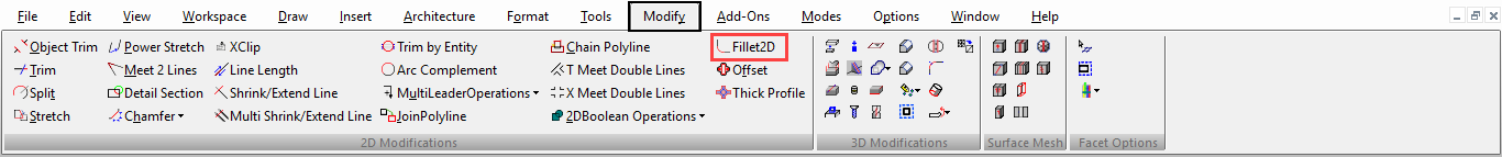
Connects two lines (either single or double lines) or arcs (except elliptical arcs) with a smoothly fitted arc. The filleted objects do not have to intersect, and they can overlap. The result is a rounded corner.
Note: You can also fillet corners with the Edit Tool . To apply fillets to a 3D polyline.
-
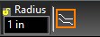
Enter the fillet radius in the Inspector Bar.
-
Select the first line or arc to fillet.
- Select the adjacent line or arc. The corner is rounded.
- If the objects overlap, they will be trimmed to create the fillet. Be sure to select the side of the object you want to remain.
Local menu options:
Polyline: Fillets all corners of a polygon or polyline in one step.
-
Enter the fillet radius in the Inspector Bar.
-
Select the multi-segmented object you want to fillet.
-
Select Polyline from the local menu or Inspector Bar.
- The fillet is applied to all corners.
- To Lines and Arcs: The resulting object is broken into lines and arcs. (The default, To Polyline, leaves the filleted object as a single object, even if the objects were originally separate.)
- In Select mode, you can verify that the fillets are separate objects.
The other local menu options apply to double lines.
Note:You can use Fillet on splines and Beziers, however the extension will be straight element of the curve, not curved continuations as they are with arcs.
Note:You can use Fillet to change an arc on a polyline, but only on arcs that are between two straight segments. Simply select the two straight segments and the arc will be adjusted to the radius of the fillet.
Fillet 3D
(Available in Platinum and Professional)
Default UI Menu: Modify/Modify 3D Objects/Fillet 3D
Ribbon UI Menu:
Creates a fillet on a 3D polyline
-
Enter the fillet radius in the Inspector Bar.
-
Select the first line or arc to fillet.
- Select the adjacent line. The corner is rounded.
Note: You can re-fillet to the same to segments with a different radius and the fillet will be adjusted.
Local menu options: Fillet All: Fillets all corners of a polygon or polyline in one step.
- Enter the fillet radius in the Inspector Bar.
- Select Fillet All from the local menu or Inspector Bar.
3. Select the multi-segmented object you want to fillet. The fillet is applied to all corners.
Intersect 2 Double Lines

(Available in all TurboCAD Variants)
Default UI Menu: Modify/Intersect Double Lines/Intersect 2 Double Lines
Ribbon UI Menu:
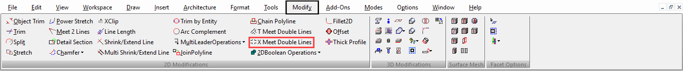
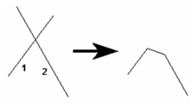
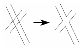
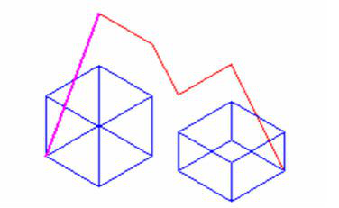
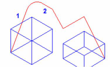
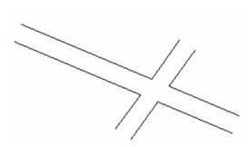
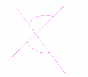
Forms an X intersection of two double lines, thereby cleaning up the intersection.
- Select both lines whose intersection you want to create.
- The X intersection is created.
Local menu options:
Join Polyline

(Available in all TurboCAD Variants)
Default UI Menu: Modify/Join Polyline
Ribbon UI Menu:
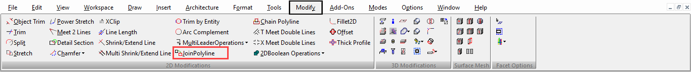
Connects two or more separate objects, connected at their endpoints, into a single-object polyline. Objects that overlap cannot be joined.
Note: If you want to create a polyline from a partial chain of segments, or if you have overlapping objects,
-
Select the tool.
-
Select the first object you wish to include in the polyline. Selection order is not important.
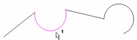
- One by one, select the remaining objects to include.
- Select Finish from the local menu or Inspector Bar.
The objects now comprise one object, as you can see in Select mode.
As of TurboCAD 2019 when you are joining a set of all Beziers the resulting object will be a Bezier. Local menu options:
Delete Original Objects: Removes the original segments, leaving only the polyline. Auto joining: Automatically selects all objects connected to the selected object. This option must be active before selecting any segments. You can select any object in the chain, not only the first or last object. If more than one segment branches from an endpoint, the chain will stop. 3D Polyline: Enables you to include objects located on different workplanes.
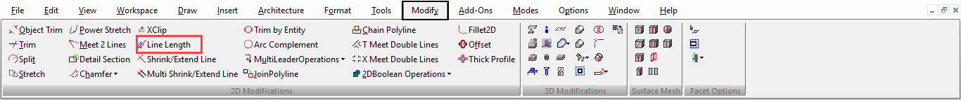
Line Length

(Available in all TurboCAD Variants)
Default UI Menu: Modify/Line Length
Ribbon UI Menu:
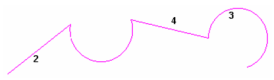
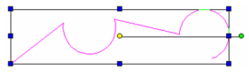
Shrinks or extends a line or line segment from either endpoint. Double lines and multi lines can also be used. If you use this tool on a polyline or polygon, any adjacent segment will move to accommodate the new endpoint.
- Select the line or line segment close to the endpoint you want to move.
- Move the cursor to set the new length, or enter the length or delta in the Inspector Bar. Negative values can be used, thereby extending the line in the opposite direction.
If another segment meets the moved endpoint, it is changed as well.
Note: You can use Line Length on splines and Beziers, however the extension will be straight element of the curve, not curved continuations as they are with arcs. 3D Polylines, and splines can also be used, but the resulting geometry will be derived relative to the objects workplane. Note: Most standard Modify tools, such as Trim, Split, and Meet 2 Lines, will work with walls.
Meet 2 Lines

(Available in all TurboCAD Variants)
Default UI Menu: Modify/Meet 2 Lines
Ribbon UI Menu:
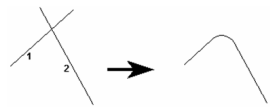
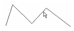
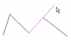
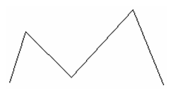
Extends two lines, double lines, walls or arcs so that their endpoints meet.
- Select the first object.
- Select the second object. The objects are trimmed or extended to meet one another.
If an object is to be trimmed, select the portion of the object you want to remain.
Local menu options: The local menu options apply to double lines.
Note: You can use Meet 2 Lines on splines and Beziers, however the extension will be straight element of the curve, not curved continuations as they are with arcs. 3D Polylines, and splines can also be used, but the terminal resulting geometry will be placed on the concurrent workplane of the two objects used. Note: Most standard Modify tools, such as Trim, Split, and Meet 2 Lines, will work with walls.
Shrink-Extend Line

(Available in all TurboCAD Variants)
Default UI Menu: Modify/Shrink-Extend Line
Ribbon UI Menu:
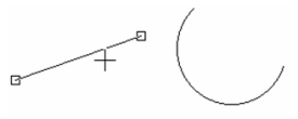
Trims or lengthens a line so that it meets another object. Double lines and multi lines can also be used.
- Select the line you want to shrink or extend. Click near the endpoint you want to move.
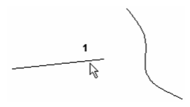
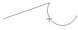
- Select the object that the line is to meet. The endpoint of the line meets the selected object.
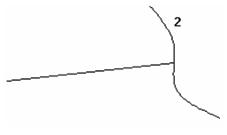
When shrinking a line, be sure to click near the endpoint that will move, otherwise the wrong part of the line will be deleted.
Local menu option: Cleanup: Relevant for double lines, makes the cutlines invisible, forming a clean intersection. Note: You can use Shrink / Extend Line on splines and Beziers, however the extension will be straight element of the curve, not curved continuations as they are with arcs. Note: Most standard Modify tools, such as Trim, Split, and Meet 2 Lines, will work with walls.
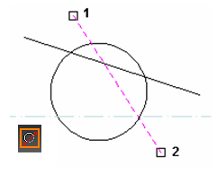
Multi Shrink-Extend Line

(Available in all TurboCAD Variants)
Default UI Menu: Modify/Multi Shrink-Extend Line
Ribbon UI Menu:
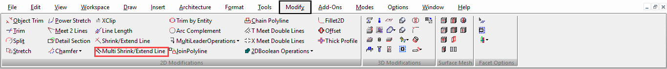
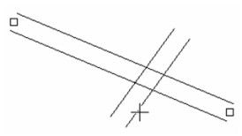
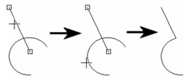
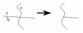
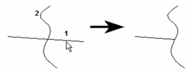
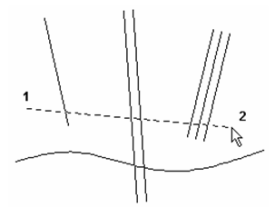
Similar to Shrink / Extend Line, trims or lengthens a group of line so that they meets another object. Double lines and multi lines can also be used.
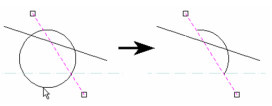
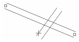
- Select two points to draw a temporary "fence" that passes over all of the lines you want to shrink or extend. Be sure the fence intersects each line closest to the endpoints you want to move.
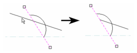
- The endpoints that will move are indicated by small squares. Select the object that the lines are to meet.
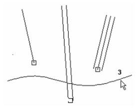
- The endpoints of the lines meet the selected object.
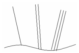
Note: You can use Multi Shrink / Extend Line on splines and Beziers, however the extension will be straight element of the curve, not curved continuations as they are with arcs. Note: Most standard Modify tools, such as Trim, Split, and Meet 2 Lines, will work with walls.
Object Trim

(Available in all TurboCAD Variants)
Default UI Menu: Modify/Object Trim
Ribbon UI Menu:
Uses one or more cutting edges to trim objects.
Note: Complex objects such as dimensions and text must be exploded before they can be trimmed. Text must be exploded twice - first into groups of polylines, then into polylines.
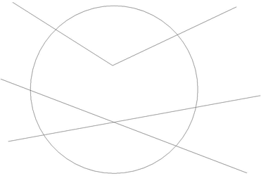
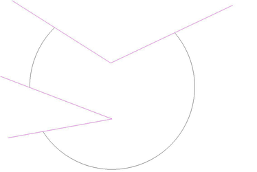
The example for Object Trim contains three objects: a circle, line, and construction line.
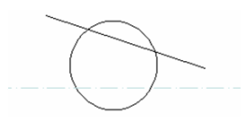
Using One Cutting Edge
- Select the object to be used as the cutting edge.
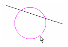
- Select the object to trim, clicking on the portion you want deleted.
- Continue selecting objects to trim, if needed.
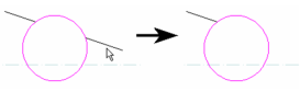
- Press Esc if you want to select another cutting edge. Select Cancel from the local menu or Inspector Bar to exit.
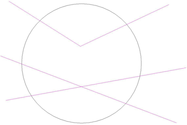
Using Multiple Cutting Edges
- Select the objects to be used as the cutting edge. Use Shift to select multiple objects.
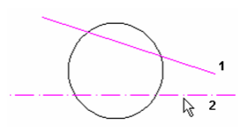
- Select the object to trim, clicking on the portion you want deleted. One or both cutting edges will be used, depending on what is selected.
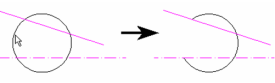
- Continue selecting objects to trim, if needed.
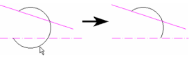
- Press Esc if you want to select another cutting edge. Select Cancel from the local menu or Inspector Bar to exit.
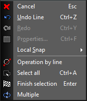
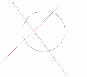
Local menu option: Operation by Line: Enables you to define the cutting edge by selecting two points.
Note: Most standard Modify tools, such as Trim, Split, and Meet 2 Lines, will work with walls.
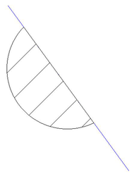
Trimming a Closed Object
 You can trim a closed or hatched object and retain closure.
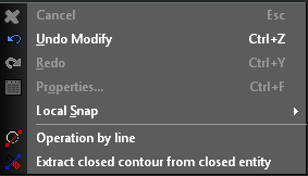
- Select the Object Trim tool.
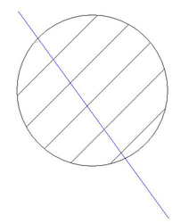
- From the local menu select the Extract closed contour from closed entity option.
- Click on the trimming object/s. Use Shift to select multiple trimming objects.
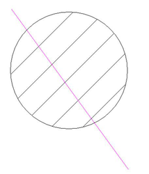
- Click on the object to be trimmed.
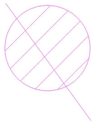
- Click on the part of the object you wish to trim.
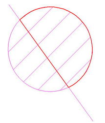
- Trimming a closed object will convert the result into a polyline so you will get the following message:
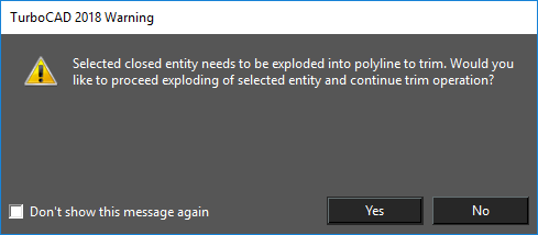
- Click Yes.
Trim

(Available in all TurboCAD Variants)
Default UI Menu: Modify/Trim
Ribbon UI Menu:
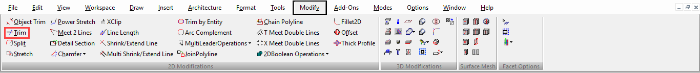
The Trim tool uses 2D objects to cut off parts of other 2D objects.
- Select the objects to be used as the cutting edges by clicking on each one. If you accidentally select an edge you can de-select it by holding down the Shift key and clicking in it.
- Once you have selected your cutting edges, right click and select Finish Selection.
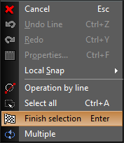
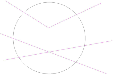
- Click on each part you wish to trim. Trimmed parts must always be between cutting edges. You can cut trimming edges as well as non-trimming objects.
The local menu also provides you the Select All option to select all 2D elements in the drawing to use as cutting edges. Additional Local Menu Options: Trim by Line: Enables you to define the cutting edge by selecting two points.
Multiple:

Multiple option lets you select more than one entities to be used as the cutting edge.
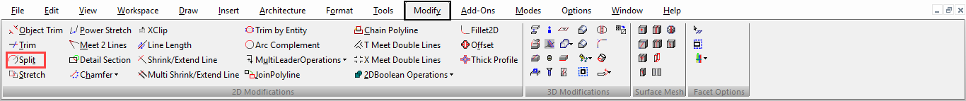
Split

(Available in all TurboCAD Variants)
Default UI Menu: Modify/Split
Ribbon UI Menu:
Divides an object into two separate objects. This tool works on any single-line or double-line object, as well as on circles, arcs, and curves. You can split by using the cursor, or by specifying a ratio in the Inspector Bar. The ratio is the length of the first resulting segment to the length of the second resulting segment. The first segment starts at the start point of the object, which depends on how the object was created.
Splitting Lines and Double Lines
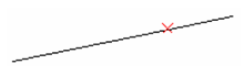
- Select the line or line segment you want to split.
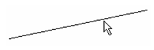
- Position the split indicator where you want the split, or enter the split ratio in the Inspector Bar.
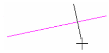
- Click to locate the split. A temporary red X indicates the location.
 Y
Y
You can verify that the line is now two separate objects by selecting one of the lines.
To split a closed object such as a rectangle or polygon, you need to create at least two splits. For each one, click on the segment you want to split.
When splitting a polyline, you place the split on one segment (line or arc), but the entire polyline is split at the selected point.
Splitting Arcs and Circles
- Select the circle, arc, or arc segment you want to split.
- Position the split indicator where you want the split, or enter the split ratio in the Inspector Bar.
- Click to locate the split. A temporary red X indicates the location. For a circle, indicate a second split point.
You can verify that the circle is now two separate objects by selecting one of the arcs.

For arcs, you only need to define one split point.
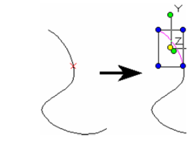
Splitting Curves
It is helpful to display the curve's frames before splitting it. This is because the split actually takes place on the line segments of the frame.
- To display the frame, open the Properties window to the Curve page and check Show Frame.
- Select the curve. Position the split indicator where you want the split, or enter the split ratio in the Inspector Bar.
- Click to locate the split. A temporary red X indicates the location. For a closed curve, select a second split point.
You can verify that the curve is now two separate objects by selecting one of the segments.
For open curves, you only need to define one split point.
Splitting 3D Curves
It is helpful to display the curve's frames before splitting it. This is because the split actually takes place on the line segments of the frame.
- Select the curve. Position the split indicator where you want the split, or enter the split ratio in the Inspector Bar.
- Click to locate the split. For a closed curve, You may want to select a second split point.
- You can then move the split off section.
Note: Most standard Modify tools, such as Trim, Split, and Meet 2 Lines, will work with walls.
Trim by Entity

(Available in all TurboCAD Variants)
Default UI Menu: Modify/Trim by Entity
Ribbon UI Menu:
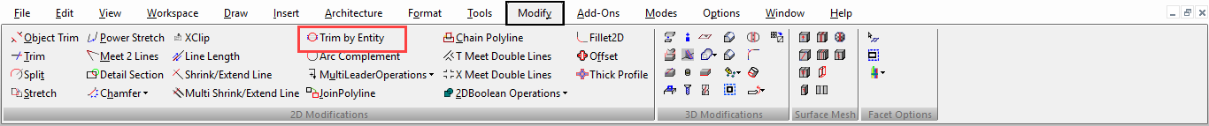
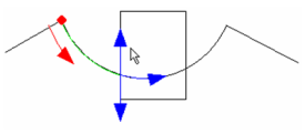
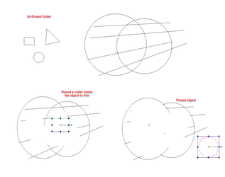
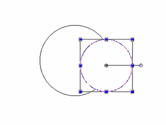
Uses an object as a cutter to trim multiple objects.
- Select a closed 2D object (cutter) to cut another object/ object placed inside it.
- Transform/ move the selected cutter to cut the object inside it.
Local menu options:
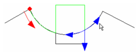
Define Entity to Trim: Enables you to cut the defined entity.
i) Enable ‘Define entity to trim’ in the inspector bar or local menu.
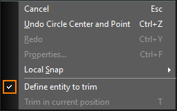
ii) Move the selected cutter to cut the defined object.
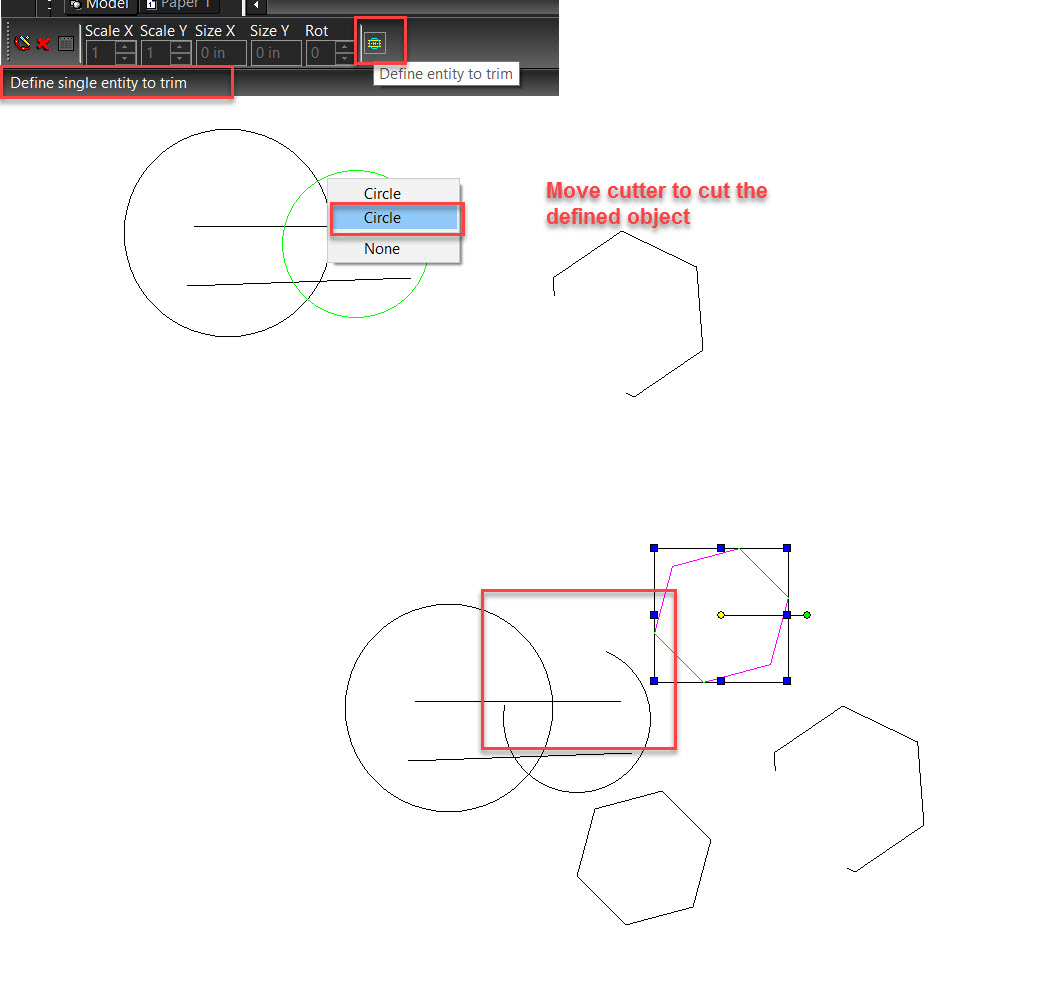
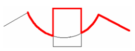
Trim in current position: Enables you to trim object in current position.
Select ‘Trim in current position’.
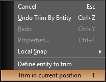
As soon as the option is selected the object is trimmed at current position.
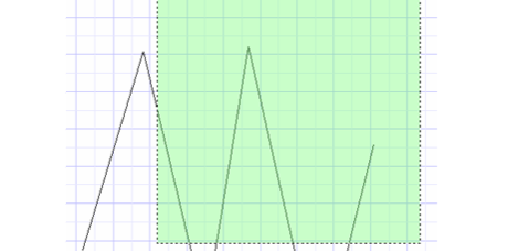
Stretch
(Available in Platinum, Professional and Deluxe)
Note: Stretch tool is not available in Designer

Default UI Menu: Modify/Stretch
Ribbon UI Menu:
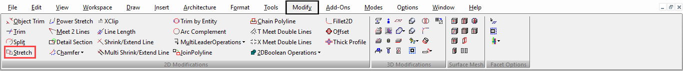
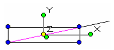
Moves a group of nodes of one or more objects by defining a movement vector.
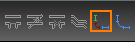
- Drag a selection window from right to left around the elements you want to stretch. Be careful to only select nodes that you want to move. If you select an entire segment (line or arc) or and entire object it will be moved and not stretched..
-
Right click and select Finish
-
Select two points to define the movement vector, or enter the length and angle in the Inspector Bar.
The selected nodes move by the defined vector.
Local menu option:
Open Window Mode: It lets you select the object by a selection window.
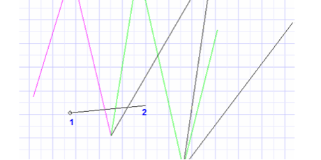
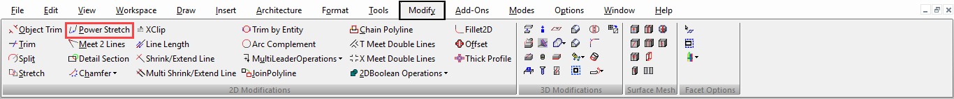
Power Stretch:

(Available in all TurboCAD Variants)
Default UI Menu: Modify/Power Stretch
Ribbon UI Menu:
Moves a group of nodes of one or more objects by defining a movement vector. You can select multiple objects by using shift key.
Local menu options:
Multiple: If this option is selected the stretch tool will continue to operate until you press ESC or select another tool. Multiple options appears in LTE workspace in local menu and inspector bar for power stretch. In default workspace, objects can be selected using shift key.
Displacement: It appears only after choosing "Finish" for selection operation. If this option is selected the node or object will be displaced by the UCS X and Y value of the point you select. For example if you click on the coordinate X= -10 and Y= 5 the displacement will be -10 in the X axis and 5 in the Y axis. Displacement option for power stretch activates in LTE workspace only.
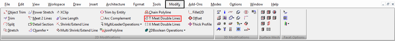
T-Meet 2 Double Lines

(Available in all TurboCAD Variants)
Default UI Menu: Modify/Intersect Double Lines/T-Meet 2 Double Lines
Ribbon UI Menu:
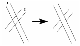
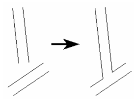
Forms a T intersection of two double lines. The first double line selected will shrink or extend to meet the intersection.
- Select the double line that will be the stem of the T. Click on the portion you want to remain.
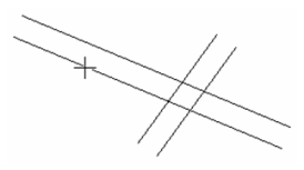
- Select the line that will be the top of the T.
The T intersection is created.
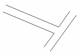
If the stem of the T does not meet the other line, it will be extended to create the intersection.
Local menu options:
Thick Profile

(Available in Platinum, Professional and Deluxe)
Default UI Menu: Modify/Thick Profile
Ribbon UI Menu:
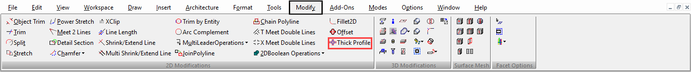
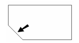
Draws grid(s) of lines/polylines/circles/arcs on plane. It is a another convenient way to create 2D profiles (closed objects with area) from polylines and curves.
You can take either an open or closed 2D Line, Arc, Polyline, or Curve (Spline or Bezier) and ‘thicken’ the profile of that entity by defining a distance on both sides of that entity where that thickening will occur.
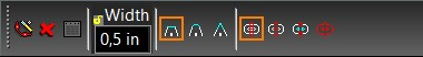
Apply thick profile tool with defined width and corners type options to groups of entities
As result user gets set of polylines, set of connected polylines (these two options are for TC versions without ACIS), region or set of sheet ACIS entities (those two are for Pro Platinum) Received entities can be used for extrudes/thick profile.
Note: The Thick profile tool automatically calculates thicken profiles accordingly to width defined for original entities
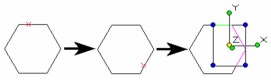
For example:
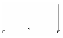
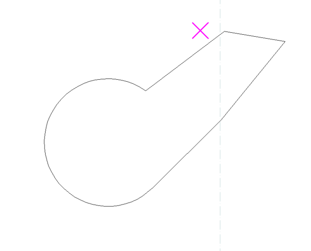
- Apply to a closed Polyline
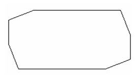
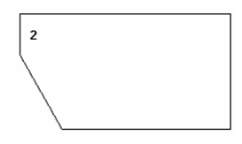
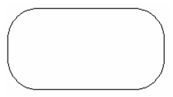
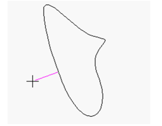
Original closed polyline with line and arc segments:
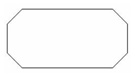
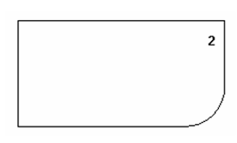
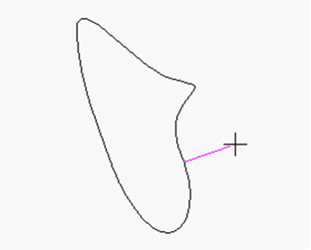
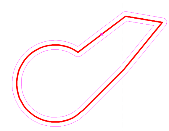
After Thicken Profile (of 15 mm each side) applied and vertices filleted:
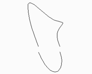
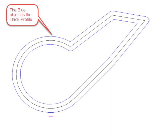
After clicking ‘Finish, final Thick Profile object:
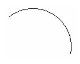
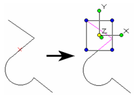
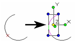
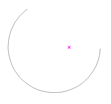
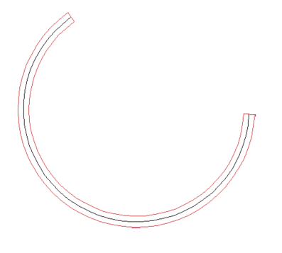
- Apply to an open Arc
Original Arc Segment:
Apply thick profile of 5 mm to each side of arc:
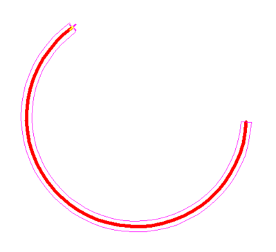
Final Thick Profile Object:
Local menu options:
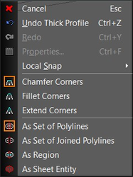
Chamfer Corners: Corners of the resulting object are chamfer.
Fillet Corners: Corners of the resulting object are fillet.
Extended Corners: Corners of the resulting object are extended.
As Set of Polylines: Resulting object will be a set of polylines.
As Set of Joined Polylines: Resulting object will be a set of joined polylines.
Region: A region will be created as a result that can be extruded.
As sheet entity: Resulting object will be an ACIS solid which can be used for sheet thicken.
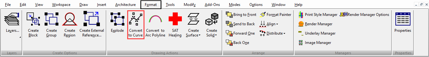
Convert to Curve

(Available in all TurboCAD Variants)
Default UI Menu: Modify/Convert to Curve
Ribbon UI Menu:
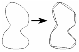
Converts a 2D object into a Bezier curve. Any single-line 2D object can be converted. Objects like double lines, dimensions, and text must be exploded first before converting.
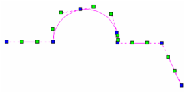
- Start with a 2D object such as a polyline. This example uses a polyline consisting of both linear and arc segments.
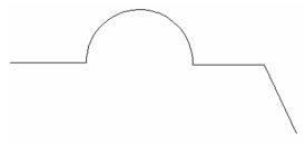
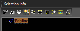
If you select the polyline and view the Selection Info Palette, you can see the object's type.
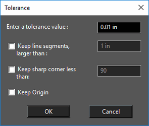
\2. To convert the polyline, select it and activate the Convert to Curve function. The Tolerance value sets the precision of the conversion; a small tolerance means high precision, and therefore more control points available for node editing.
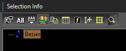
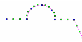
The polyline is replaced by a Bezier curve. This can be verified in the Selection Info Palette.
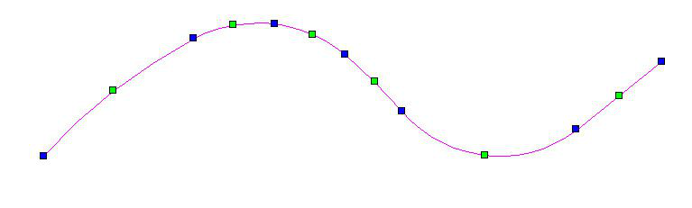
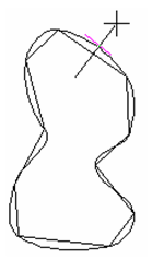
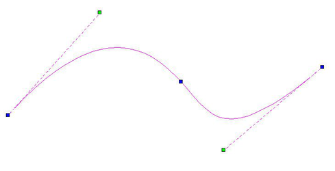
If you edit the curve with the Edit Tool, you can see the control points available for changing the curve's shape. (For details on Bezier options, . This curve used a low precision (Tolerance = 0.1).
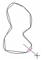
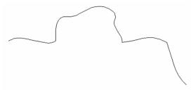
This curve used a higher precision (Tolerance = 0.001).
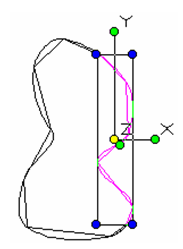
Nodes and control points can be moved to change the curve's shape.
Convert to curve also works on 2D objects that are converted into 3D by entering a thickness in the 3D page of the Properties.
Sharp corners will remain sharp when two adjacent line segments cannot be approximated by an arc within the specified tolerance. This could happen when the vertex is too "sharp" which is defined by vertex angle, line lengths, and tolerance.
Convert to Arc Polyline

(Available in Platinum, Professional and Deluxe)
Default UI Menu: Modify/Convert to Arc Polyline
Ribbon UI Menu:
Converts a 2D object into a Polyline composed of arcs. Any single-line 2D object can be converted. Objects like double lines, dimensions, and text must be exploded first before converting.
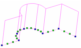
- Start with a 2D object such as a polyline. This example uses a polyline consisting of both linear and arc segments.
- To convert the polyline, select it and activate the Convert to Arc Polyline function. The Tolerance value sets the precision of the conversion; a small tolerance means high precision, and therefore more control points available for node editing.