Terrain
(Available in Platinum and Professional)
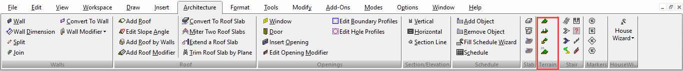
Default UI Menu: Architecture/Terrain
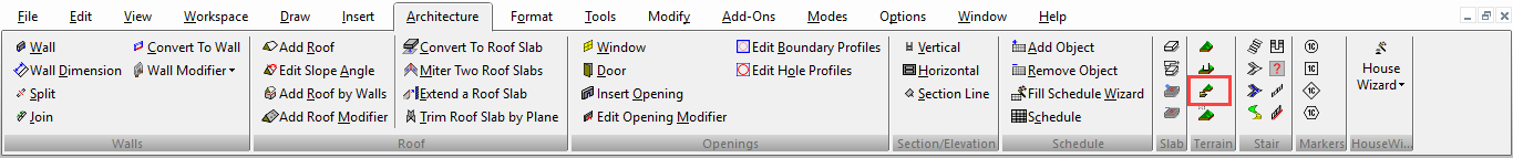
Ribbon UI Menu:
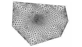
Creates a topographical terrain, represented by triangulated network. You can create a terrain from scratch, or import coordinates from a file.
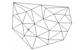
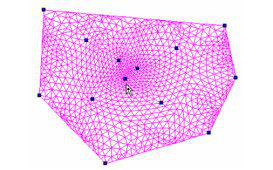
- Activate Terrain, and click points to define the outer boundary (or enter coordinates in the Coordinate Fields). As you click points, the surface triangulates.
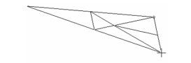
- Continue defining the outer boundary.
- Define interior points as well. Each point you define will become a node you can edit. You do not need to define all nodes now; you can add nodes later.
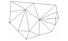
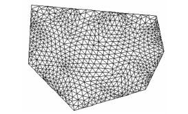
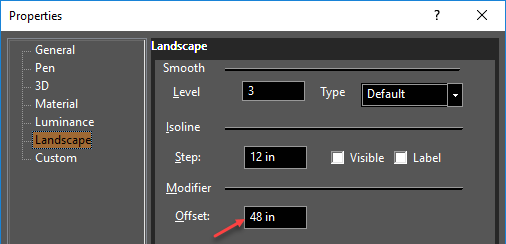
- Open the terrain's Properties to the Landscape page. Under Smooth, increase the Level.
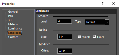
This increases the level of triangulation, resulting in a more accurate surface.
- Activate the Edit Tool on the terrain. Each point you defined when creating the terrain is represented as a node.
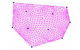
Note: For details on this tool,
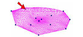
- If you want to add more nodes, right-click where you want the new node and select Add Node.
- To modify the terrain, click a node and use the Coordinate Fields to change its Z position. You can also drag a node while in a Front or Side view. Adjacent nodes will remain in place.
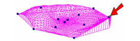
- You can also change the elevation of nodes along the boundary.
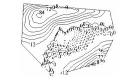
- Switch to World Plan. This view shows the terrain as a series of isolines, each labeled with its elevation.
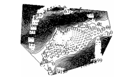
- In the Landscape page, change the Step. In this example, an isoline will be displayed every 12 inches.
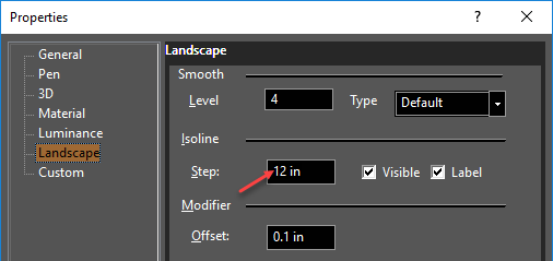
This makes the isoline display less dense.
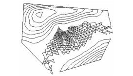
- Uncheck Label.
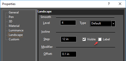
This removes the elevation value from each isoline.
- Uncheck Visible.
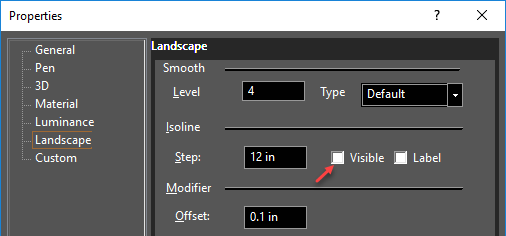
This removes the isoline display.
If isolines are displayed, when you move out of World Plan view, they will not be visible.
Import Terrain

Default UI Menu: Architecture/Import Terrain
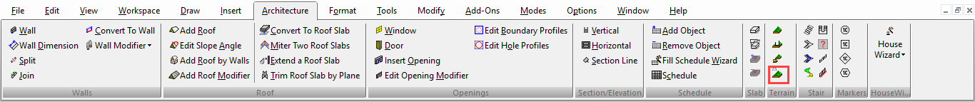
Ribbon UI Menu:
Terrain data you can import must be listed in a .txt or .xyz file. The format for each coordinate should be X, Y, and Z values, separated by commas or spaces. Activate Import Terrain, and define the original point. This is where the center of the terrain will be placed. Then select the data file.
Terrain from Selected Points
Default UI Menu: Architecture/Terrain from Selected Points
Ribbon UI Menu:
Creates a terrain from a set of selected points. The points must all have the same Z coordinate. For details on points. To create the terrain, first select the points, then activate Terrain from selected Points.
Terrain Modifier
Default UI Menu: Architecture/Add Terrain Modifier
Ribbon UI Menu:
You can add or remove material from a terrain around a closed, 2D profile.
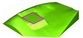
- Start with a terrain, and create a closed 2D shape, such as a rectangle.
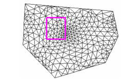
- In this example, the shape is placed vertically so that part of it is below the terrain, and part of it is above.
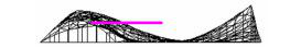
- Activate Terrain Modifier, and select the terrain to modify. Then select the closed shape. Material is added or removed as needed to meet the shape.
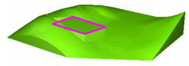
- To slope the terrain around the modified shape, add an Offset value.
This is the result: