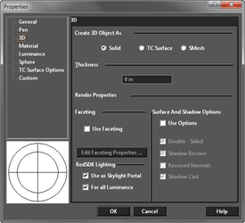
3D Properties
Controls how objects are created, and their materials.
Note: For options that control how 3D objects are displayed,
 Create 3D Object As: Choose between Solid (ACIS representation) and TC Surface (TurboCAD representation), or SMesh, (Smooth Surface Mesh). 3D objects are created as solids by default, but you can change this Properties setting for all 3D tools, or for individual objects.
Solid objects are created using the ACIS solid modeling engine. Solids are more realistic than surfaces, because objects have volume as well as shape. The solid model assumes that a 3D object comprises a framework, a "skin" (set of surfaces) encasing the framework, and inner "body."
TC Surface objects are created using the TurboCAD internal graphics engine. The "inner body" concept does not apply to surfaces, but when an object is trimmed or cut, the resultant object is entirely covered by surface elements. You can create surfaces that are ACIS objects by converting existing objects.
Smooth Mesh - SMesh A smooth mesh or "smesh" is a surface object which can be form organic shapes more easily than traditional solids and surfaces. This can be accomplished by specifying a smoothing value to the smesh.
Create 3D Object As: Choose between Solid (ACIS representation) and TC Surface (TurboCAD representation), or SMesh, (Smooth Surface Mesh). 3D objects are created as solids by default, but you can change this Properties setting for all 3D tools, or for individual objects.
Solid objects are created using the ACIS solid modeling engine. Solids are more realistic than surfaces, because objects have volume as well as shape. The solid model assumes that a 3D object comprises a framework, a "skin" (set of surfaces) encasing the framework, and inner "body."
TC Surface objects are created using the TurboCAD internal graphics engine. The "inner body" concept does not apply to surfaces, but when an object is trimmed or cut, the resultant object is entirely covered by surface elements. You can create surfaces that are ACIS objects by converting existing objects.
Smooth Mesh - SMesh A smooth mesh or "smesh" is a surface object which can be form organic shapes more easily than traditional solids and surfaces. This can be accomplished by specifying a smoothing value to the smesh.
Tip: You can explode a solid object twice to turn it into an exploded (node-editable) surface object.
Thickness: Relevant for 2D objects. Assigning a 2D object a thickness makes it a 3D object. Closed 2D objects become solid or surface volumes; open objects (lines, arcs) become surfaces.
Note: The thickness is assigned perpendicular to the workplane in which the object was drawn, regardless of the current workplane.
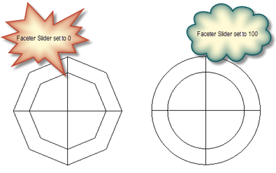
Object Specific Faceting
Faceting can be controlled on an individual object basis via the Properties of the object. Object specified faceting overrides the global setting in the ACIS settings.
 For details on the Faceter settings see:
Two entities with new faceter options:
For details on the Faceter settings see:
Two entities with new faceter options:
Render Properties
These properties are used to speed up rendering and have more efficient memory use. These properties work only in render modes and do not affect wireframe or hidden line modes.
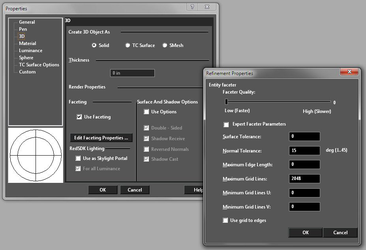
Faceting
A set of options that define the faceter mode for the object. Faceting options can be enabled only for ACIS (solid) objects. Use Faceting: This option turns the local faceter mode on/off. When it is off( by default), this section does not affect the render. If it is on, then render will use the local faceter mode instead of the one from the ACIS dialog to control rendering of this object. Edit Faceting Properties: This button opens the dialog with local faceter mode settings. Dialog parameters fully match the parameters available in the ACIS Custom parameters.
Section Surface And Shadows
This set of additional options define the behavior of the graphic during rendering. Use Options: This option turns the use of this set of options on/off. If this option is off (by default), then these options do not affect the render. If it is on, then rendering will use the parameters from this section for this object. Double-Sided: (Off by default) When On this option indicates to the rendering engine that the primitive should be treated as double-sided. By default a primitive is single-sided. Reversed Normals: (Off by default) When On this option indicates to the rendering engine that orientation of normals will be reversed. Shadow Receive: (On by default) When Off this option indicates to the rendering engine that the primitive will no longer receive any shadows. Shadow Cast: (On by default) When Off this option indicates to the rendering engine that the primitive will no longer cast any shadows.
Skylight Portals
If the option Use as Skylight Portal is on, the entity will be used as a portal geometry for skylight luminances. The option is 'Off' by default.
Portals are useful for interior scenes for example, where sky light is entering by small openings which are difficult to sample efficiently. By marking explicitely the openings using portals, the engine can render difficult situations at a much higher quality in less time.
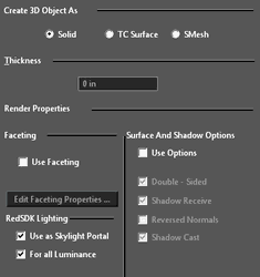 For all Luminance: If On the portal will be used for all luminances with skylight in scene, no matter how this sky light was created (drawing luminance or graphic luminance). If Off the portal will be used for this objects luminance only. The option is enabled if option only if Use as Skylight Portal is On. The option is 'On' by default.
Using portals
Portals are objects (surfaces) that control the flow of photons from the light source. More precisely: the spatial configuration of the photon's flow.
The simplified algorithm is the following: if the photon has not passed through the portals, it is not considered in the calculation of illumination and the CPU time is not spent on it. Instead of it the next photon is launched (generally at random). This continues until the number of photons passing through the portals will not be equal to the target parameters of the light source. In our case it is a sky light (RedSDK supports only sky lights for the portals). In the case of absence of portals all launched photons are involved in the calculation of the illumination.
So, portals allow you to concentrate the quality and the intensity of the light in the right places of the scene. This facilitates the creation of a scene with proper lighting and improves the speed of calculation.
The main purpose of the portals is using them for the openings through which the outer sky light penetrates. Portals need not to be rectangular necessarily. The portal may consist of any set of surfaces. At the same time you should not make the portal very complicated (for example as an ADT window), because of the additional time is required to clarify whether the photon passes through a portal or not. Ideally it should be 1 rectangular facet.
In TurboCAD any 3D primitive can be a portal. This simplifies creation of portals. It should be noted that in this case the geometry of this primitive is not loaded into the scene. In other words an option 'Use as skylight portal' is similar to the option "Load to render luminance only".
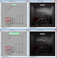
Below is shown the effect of the portal's size on the lighting quality and intensity. By increasing the size of the portal 2 times the quality worsens 4 times (at the square).
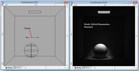
 Below is shown how it is possible to highlight the places in the scene by using the portal's position.
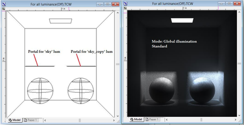
 Below is shown how it is possible to highlight the places in the scene by turning the option For all luminance Off.