Tracing
(Available Only in Platinum, Professional, and Deluxe)
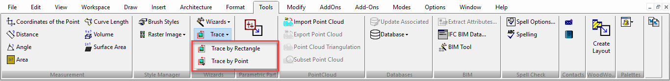
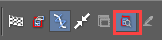
The Trace tools originate from the stand-alone ScanPro application, which has now been incorporated into TurboCAD. They enable you to create 2D raster-to-vector tracings of inserted pictures or of geometric objects. Trace tools are available on the Tools toolbar, which you can display by right-clicking in any toolbar area and selecting Tools. Before creating a tracing, it's important to understand the local menu options, since these greatly affect the appearance and quality of the trace. Trace Options: Settings for trace quality. The General page provides options for the Picture Type. The Detail Level and Color Level values update with the picture type.
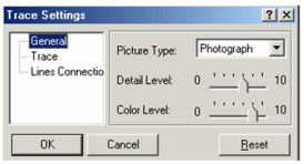
The Trace page controls the quality of the tracing.
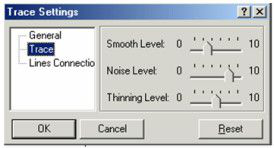
Smooth Level: Reduces jags and discontinuities in lines and curves.
Noise Level: Reduces spots.
Thinning Level: Reduces line widths.
The Lines Connection page contains parameters relevant when Connect Lines is activated.
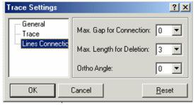
Max Gap for Connection: The largest gap which will be closed when connecting lines.
Max Length for Deletion: The largest segment that can be deleted, i.e., breaking the lines on either side.
Ortho Angle: The angle at which line segments will be joined into polylines.
Curve Recognition: Traced polylines will be created as curves. Otherwise they will be created as lines and polylines.
Preview Mode: A trace preview will appear in magenta over the image.
Tracing Colors: By default, all colors will be used for tracing. This option is used when you want to trace around only selected colors.
The following two options are relevant only for Trace by Point: Show / Hide Trace Rectangle: Toggles the display of the tracing rectangle, defined by its aperture size.
Nearest Graphic Only:
Traces only the object closest to the tracing rectangle's center, identified by crosshairs.
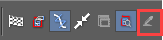
Trace by Point
(Available in Platinum, Professional and Deluxe )
This tool is basically the same as Trace by Rectangle, with a different way of defining the trace area. The selection area is sized by the Aperture field, which is the length of each side of a square whose center is represented by crosshairs.
Using the same example picture as for Trace by Rectangle, place the cursor at the center of the desired selection area.
The results are the same - all objects within the area will be traced. If Nearest Graphic Only is active, then only the object closest to the crosshairs will be traced.
Trace by Rectangle
(Available in Platinum, Professional and Deluxe)
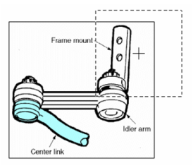
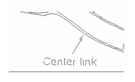
Creates a tracing of all objects within a selection rectangle. This example uses the following inserted picture:
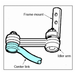
To easily see the results of the trace, it is good practice to place the inserted picture on its own layer which can then be blanked.
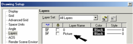
1.Activate Trace by Rectangle and define the selection rectangle. (You can also use fields in the Inspector Bar to control the rectangle size.) If Preview Mode is on, the traced lines will appear in magenta.
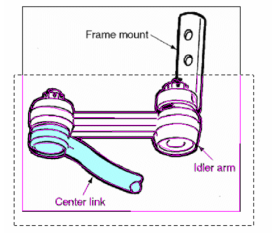
2.Select Finish from the Inspector Bar or the local menu.
3.Move or delete the picture, or simply blank its layer, to see the tracing.
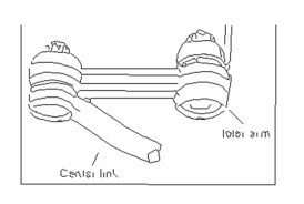
In the above example, the text lines did not trace completely. To improve trace quality, you can increase the zoom of the traced objects.
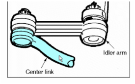
The previous example traced around all colors. If you only wanted to trace around the shaded area of the center link, you would use the Tracing Colors option, which must be set before starting the trace.
When the Select Colors to Trace window opens, click on the colors you want to include. The colors then appear as blocks in the window.
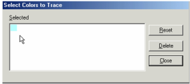
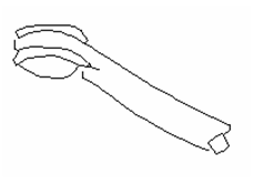
The result is a trace only around the center link.
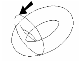
Note: Trace colors remain active for future traces, so it is important to click Reset (to zero colors) if necessary. In addition to pictures, you can also trace around geometric objects. This example is a solid torus, rotated and displayed in Hidden Line mode.
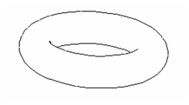
The trace is created in the current viewing plane. The result is shown below, rotated so that the 2D trace can be seen: