Construction Geometry
Construction Geometry
(Available in all TurboCAD Variants)
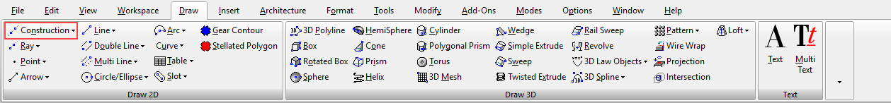
Default UI Menu: Draw/Construction
Ribbon UI Menu:
Construction geometry tools enable you to place temporary lines and circles in your model. Construction geometry are not drawing objects; they are used as references.
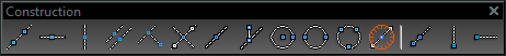
Snaps can be used on construction geometry for creating model geometry, as well as other construction geometry. However, because construction lines are infinite, the Vertex and Middle Point snaps are not available. You can display the Construction toolbar by right-clicking in any toolbar area and selecting Construction.
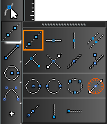
 These tools are also available on the fly-out toolbar from the Drawing Tools.
Note: You can use construction entities with the Trim tool to trim other drawing entities, however you cannot trim construction entities themselves.
Clearing and Hiding Constructions
Default UI Menu: Edit / Clear / Construction or Edit / Clear / All Constructions
Ribbon UI Menu:
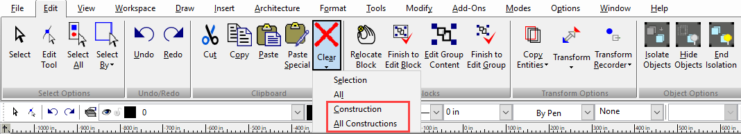
You can clear construction objects via the Edit menu. Edit / Clear / Construction enables you to delete a single construction object. Edit / Clear / All Constructions deletes all construction geometry. To hide constructions, you can hide the $CONSTRUCTION layer. Open the Layers window and uncheck the visibility box for this layer.
Construction Geometry Properties
Construction objects are placed on layer "$CONSTRUCTION". By default, the layer color is light blue, and the line style is dash-dot. You can change construction geometry color and line styles via the layer manager.
Note: It is not recommended to place model geometry on the $CONSTRUCTION layer. If the color and line style of objects are set to By Layer, the objects will appear as construction geometry. It is also not recommended to change the line style to Continuous.
Creating Construction Geometry
Default UI Menu: Draw/Construction
Ribbon UI Menu:
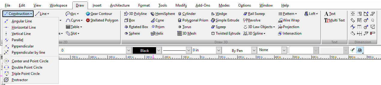
Several types of construction lines and circles are available.
Construction-Angular Line

- Select a point through which the construction line will pass. Select a second point, or enter the slant in the Inspector Bar.
2. The construction line is created, with the properties assigned to the construction layer.
Construction-Horizontal Line, Vertical Line


- Select the point through which the construction line will pass.
- Continue creating construction lines of the same type, and select Finish when done.
Construction-Parallel

- Select the line to which the construction line will be parallel. You can also select a construction line.
2. Select a point through which the construction line will pass, or enter the offset in the Inspector Bar.
Tip: To make multiple construction lines separated by the same distance, lock the Offset field in the Inspector Bar, and create parallel lines from each successive line.
Construction-Perpendicular

- Select the line to which the construction line will be perpendicular. You can also select a construction line.
2. Select a point through which the construction line will pass.
Construction-Center and Point Circle
 Creates a construction circle by defining its center and a point on its circumference.
- Select the circle centerpoint. Move the cursor to begin to size the circle.
2. Click to create the circle, or enter the radius, diameter, or circumference in the Inspector Bar.
Construction-Double Point Circle
 Creates a construction circle by defining two opposite points on its circumference.
- Select a point on the circle circumference.
2. Select the point on the opposite end of the diameter line, or enter the radius, diameter or circumference, and angle of the diameter line in the Inspector Bar.
Construction-Triple Point Circle
 Creates a construction circle that passes through three points.
- Select the first point on the circumference.
2. Select the second point.
3. Select the third point.
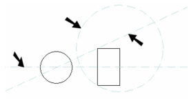
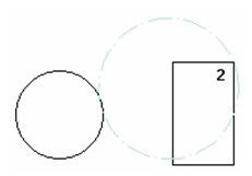
Construction-Perpendicular by Line
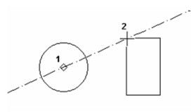
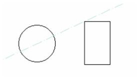
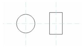
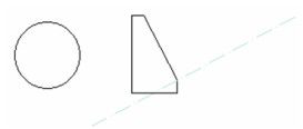
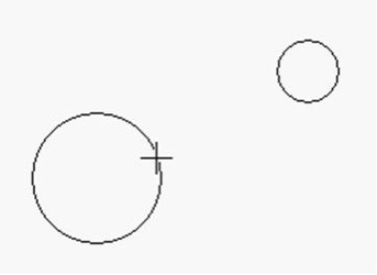
 Creates a construction line perpendicular to a line defined by two points. Start with two circles, We will create a construction line halfway between the centers of the two circles perpendicular to the axis between the two centers.
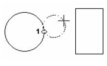
- Select the tool, then snap to the center of the first circle.
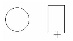
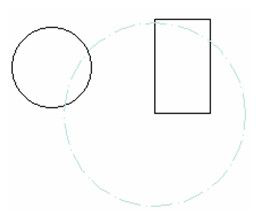
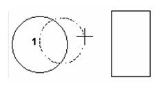
2. Move the cursor. Notice that the preview of the construction line is parallel to the line you are dragging out.
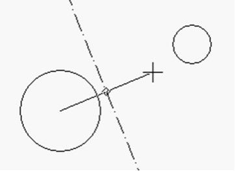
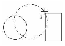
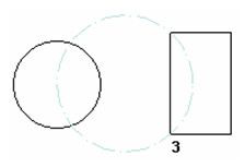
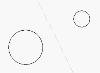
3. Snap to the center of the other circle to set the construction line.
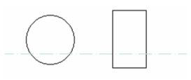
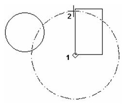
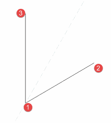
Construction-Bisection
 Creates a construction line which bisects an angle
- Click on the first point. this will be thevertex of the angle to be bisected.
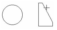
- Click on the second point. this will be the first edge of the angle to be bisected.
- Click on the third point. this will be the second edge of the angle to be bisected.
- Move the cursor. Notice that the preview of the construction line is parallel to the line you are dragging out.
2. Snap to the center of the other circle to set the construction line.
Editing Construction Lines
You can use the Edit tool to adjust the nodes of construction lines and rays. You can split a construction line into two rays by using the Split tool.
Printing Construction Geometry
While printing, you can choose whether or not construction geometry will be printed as part of your drawing. This option is set in the Page Setup.
Protractor


Default UI Menu: Draw/Construction/Protractor
Ribbon UI Menu:

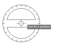
The protractor creates a construction line in any desired orientation in 3 dimensions. The protractor tool provides a visible protractor wheel to ease visual placement of the resulting construction line. To use the protractor: First, select the tool located with the construction tools. Second, position the protractor in the desired location then click in the drawing to place the center of the protractor, or specify a location via the Command line or Inspector bar.
 Specify a base orientation for the protractor by:
- Slicking in the drawing to designate the base angle. or
- Specify a point via the Command line or Inspector bar to designate the base angle.or
- Specify an angle via the Command line or Inspector bar.
Specify the final angle for the construction line by:
- Slicking in the drawing to designate the base angle.or
- Specify a point via the Command line or Inspector bar to designate the base angle.or
- Specify an angle via the Command line or Inspector bar.
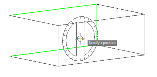
Orienting the Protractor The protractor will automatically align to any 3D surface you hover over. Surface will highlight as you hover over them. Once you place the cursor location the resulting construction line will be oriented to the surface you have specified. 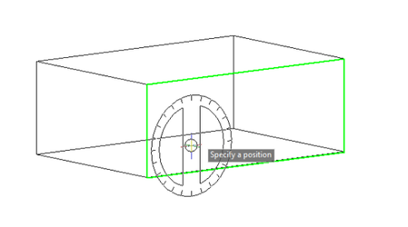
If the surface you wish to align to is located behind another surface you can use the Page Down and Page Up button on the keyboard to cycle through the available surfaces until the desired surface is highlighted.
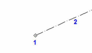
Rays
Rays are a special type of construction line with only one end point extending infinitely in one direction.
Angular Ray

Default UI Menu: Draw/Angular Ray
Ribbon UI Menu:

- Select a point for the end of the ray will pass. Select a second point, or enter the slant in the Inspector Bar.
- The ray is created, with the properties assigned to the construction layer.
Horizontal Line, Vertical Line


Default UI Menu: Draw/Construction/Horizontal Line, Draw/Construction/Vertical Line
Ribbon UI Menu:

- Select the point through for the end of the ray.
- Continue creating ray lines of the same type, and select Finish when done.
Local menu options: Flip: the Flip option changes the direction of the ray 180 degrees.