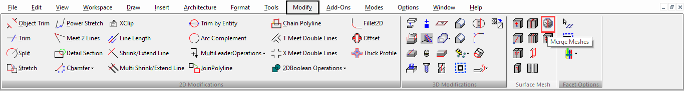
Smooth Mesh SMesh
(Available only in Platinum)
Default UI Menu: Modify/Modify 3D Objects/Surface Mesh
Ribbon UI Menu:
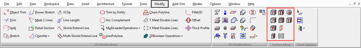
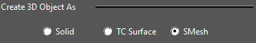
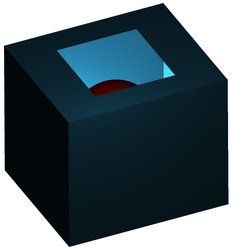
A smooth mesh or "smesh" is a surface object which can be form organic shapes more easily than traditional solids and surfaces. This can be accomplished by specifying a smoothing value to the smesh.
3D tools for SMesh Creation
Most Standard 3D tools can be used to create primitive 3D objects can be used to create a basic smesh. In the 3D properties of most 3D tools there is an option to create the object as a smesh.
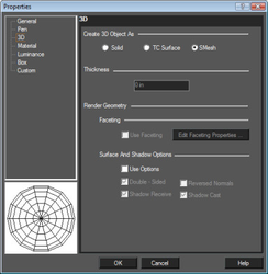
In addition some of the 3D tools also allow for the defining of the tessellation and smoothness of the resulting smesh.
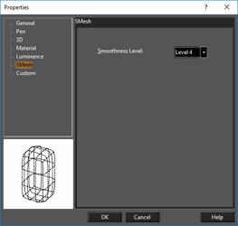
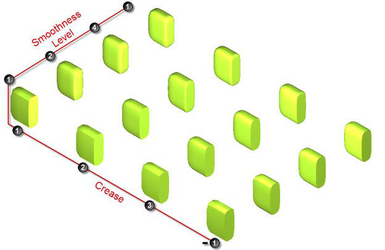
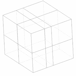
Smoothness Level
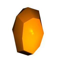
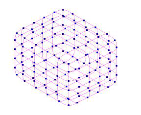
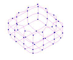
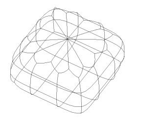
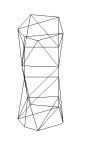
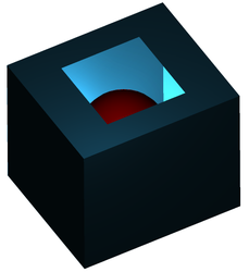
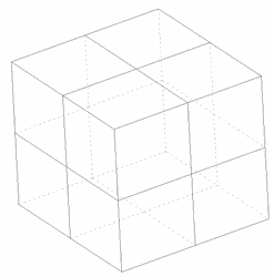
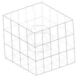
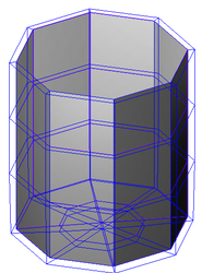
The smoothness level for a smesh sets how smooth the transition will be on the smesh for each face and between faces. Smoothness works by creating hidden subdivisions of the surface. The higher the level is set the higher the number of subdivisions. The Smoothness level can be set from the minimum of one to the maximum of 4. A cube set to one tessellation in all values will look like this when the Smoothness level is set to 1:
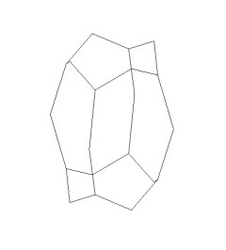
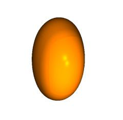
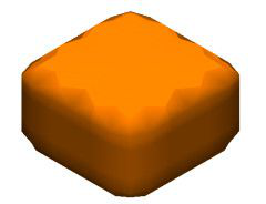
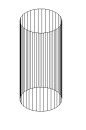
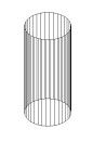
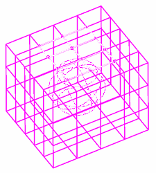
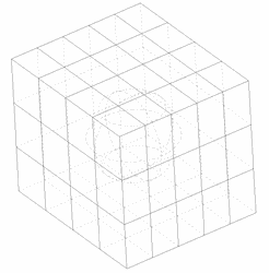
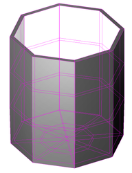
And Like this when the smoothness level is set to 4:
Warning: Setting a high value for the Smoothness level on object with a large number of faces will slow the application down significantly.
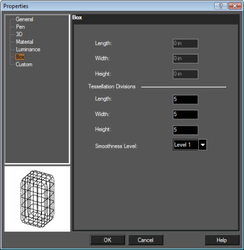
Tessellation Divisions
These divisions refer to the number of surface segments that will be created on the resulting object. The number and type of inputs will vary depending upon the object type. For example, for a Box there are three values (Length, Width, Height), for a Sphere the inputs are called "segments" and are latitudinal and longitudinal. The minimum value for a division/segment is 1, while the practical maximum value is 14. Above that value deformation may begin to occur, and the application slows down significantly.
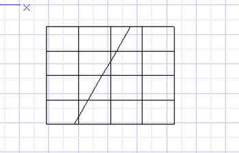
SMeshes and Exploding the Primitive
While it is possible to create a smesh using a 3D primitive tool like Box, there are limitations on what you can do with that smesh. Most smesh editing is done with the Edit tool, but smesh objects created with standard 3D tools will function as that primitive type when you use the Edit tool.
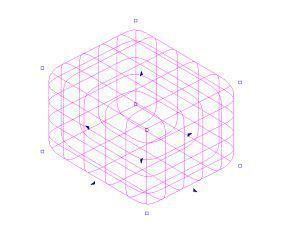
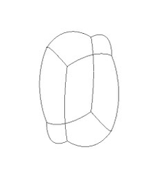
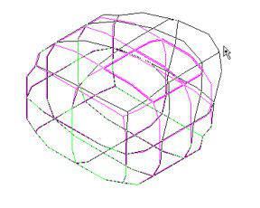
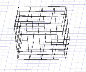
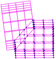
In addition many 3D tools like loft and prism do not allow you do create a smesh directly. To get the maximum utility out of the 3D objects you need to explode the original 3D object. Exploding a box smesh will result in the following when using the Edit tool. When you do this you will lose the ability to set the number of tessellations, because this is no longer a "box", but you will gain access to much more.
To get a smesh for something like a loft you must first explode the loft, and then you must set the object 3D property to the SMesh option.
 After you have a smesh you will still be to set the smoothness level, but this option will now be located in the smesh section of the objects properties.
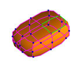
Edit Tool and SMeshes
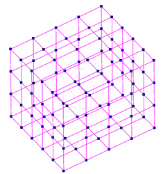
The full power of smeshes is exposed via the Edit tool. The Edit is used to refine, simplify, move, and transform smeshes by editing their nodes, edges, and faces.
Moving SMesh Nodes, Edges and Faces
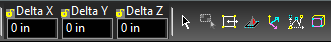
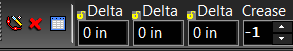
To move selected nodes, edges or faces you can drag or specify delta values. To drag your selection, click and hold the left mouse button on one of the selected nodes, and then drag-and-drop. You must use the nodes to drag the edges and faces as well.
Alternately you can type values into the Delta X, Delta Y, and Delta Z fields, and then press Enter.
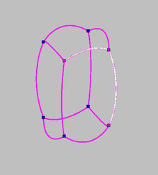
Selecting SMesh Edges
To select the edge of a smesh, hold down the Shift key and click on that edge. The selected edge will be highlighted. You can select as many edges as you want while holding the Shift key, and you can deselect as well. There is no way to select multiple edges with a fence, only direct selection is available. When you select an edge both nodes associated with that edge will become selected.
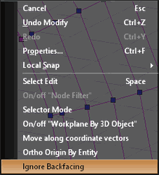
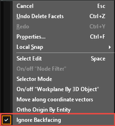
Ignore Back facing
Selecting the Ignore Back facing option will limit the selection face, nodes, and edges to those on the side of the object facing the user.
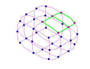
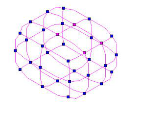
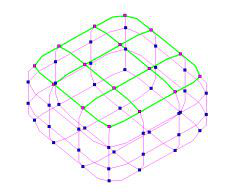
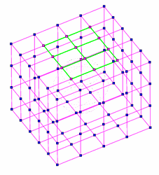
Selecting SMesh Faces
To select the face on a smesh, hold down the Shift key and click in the white space of that face, being careful to avoid edges and nodes. Sometime there may be multiple faces at a position, stacked one behind the other, however only the closest face will be selected. The selected face will be highlighted. You can select as many faces as you want while holding the Shift key, and you can deselect in the same manner. There is no way to select multiple faces with a fence, only direct selection is available. When you select a face all of the edges and nodes associated with that face will become selected.
Ignore Backfacing
Selecting the Ignore Back facing option will limit the selection face, nodes, and edges to those on the side of the object facing the user.
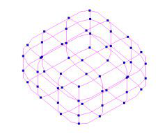
Selecting SMesh Nodes
With the Edit tool active select the object you wish to edit.
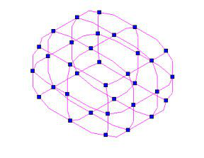
A node can be selected just by clicking on that node. Selected nodes will be highlighted.
You can select multiple nodes by holding down the Shift key and selecting each node in turn. You can deselect any highlighted node by holding down the Shift key and selecting that highlighted node.
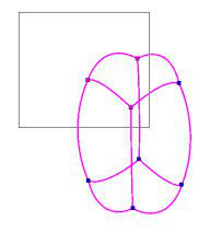
You can also use fence selection to select multiple nodes. To use fence selection, click and hold the left mouse button and drag a rectangular fence around the nodes you wish to select. It is important to note that you cannot begin a selection fence while over the object; you must start the fence away from the object. You can use the Shift key with the selection fence to add/subtract multiple nodes. If you hold down the Shift key while using the selection fence any node within the fenced area which are not already selected will be added to the selection, while any nodes that are already selected will be de-selected.
Ignore Backfacing
Selecting the Ignore Backfacing option will limit the selection face, nodes, and edges to those on the side of the object facing the user.
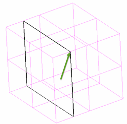
Extruding SMesh Faces
Default UI Menu: Modify/Modify 3D Objects/Surface Mesh/Extrude Face
Ribbon UI Menu:
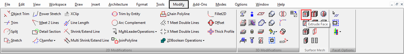
Faces can be extruded from/into the body of an object to create extensions or depressions. This moves the original face and adds new faces along the axis of movement. You can extrude multiple faces simultaneously. You cannot extrude if the Edit tool is in Selector Mode.
To extrude select the face/s you want to extrude using the Edit tool.
Hold down the Shift key and click on the face you want to select.
Then, select the Extrude Face option from the local menu or the Inspector bar.
 A Height field will appear. Type a value into the field, and then press the Enter key.
 Positive values will extrude away from the body of the object, negative values will extrude toward the body of the object.
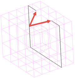
Along Facet Normal
Once the Extrude option is active another option called Along Facet Normal will appear. This option is ON by default. Along Facet Normal forces the extrusion to move parallel to the normal of the face/facet.
The normal is the direction to which the face is oriented. It is the imaginary line, perpendicular to the center of the face extending out into space.
When Along Facet Normal if OFF you can extrude the face by dragging it anywhere in space, by dragging the associated nodes or you can use the Delta X, Delta Y, and Delta Z fields to specify a location for the extrusion.
SMesh Merging
Default UI Menu: Modify/Modify 3D Objects/Surface Mesh/Merge Smesh
Ribbon UI Menu:
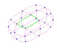
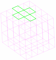
Merging is the opposite of refining. It takes all of the selected faces and creates one larger face. All of the faces must be contiguous (neighboring) and share edges, or they cannot be merged. The Edit tool Selector mode must be OFF or the Merge option will be unavailable.
To merge faces, first select the desired faces.

Once all of the faces are selected, choose the Merge Facets option from the local menu or Inspector bar.
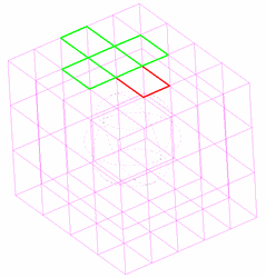
Refining
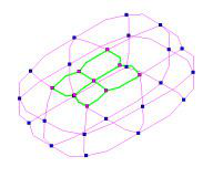
Sometimes it is desirable to increase the number of faces in a given area. This is called refining and can be done to any selected face. You cannot refine if the Edit tool is in Selector mode, or if the Smoothness Level of the object is set to none.
To refine a face or set of faces, first select them with the Edit tool. Then select the Refine Face option from the local menu or from the Inspector bar.
 The face will be refined based on the Smoothness Level. In essence the invisible subdivisions are converted into new faces for the object. The degree of refinement is as follows:
If the Smoothness Level = 1 the then face (with four edges) will be divided into 2 x 2 (4 new faces) If the Smoothness Level = 2 the then face (with four edges) will be divided into 4 x 4 (16 new faces) If the Smoothness Level = 3 the then face (with four edges) will be divided into 8 x 8 (64 new faces) If the Smoothness Level = 4 the then face (with four edges) will be divided into 16 x 16 (256 new faces)
At a minimum, one new face will be made for each edge of the face. The general rule of thumb for the algorithm is:
Where F is final number of faces, N is the Number of initial edges, S is the Smoothness Level.
F=N(2^S)
So if the smoothness Level is 3, and the number of edges is 6, the resulting number of faces will be 96.
The face will be refined based on the Smoothness Level. In essence the invisible subdivisions are converted into new faces for the object. The degree of refinement is as follows:
If the Smoothness Level = 1 the then face (with four edges) will be divided into 2 x 2 (4 new faces) If the Smoothness Level = 2 the then face (with four edges) will be divided into 4 x 4 (16 new faces) If the Smoothness Level = 3 the then face (with four edges) will be divided into 8 x 8 (64 new faces) If the Smoothness Level = 4 the then face (with four edges) will be divided into 16 x 16 (256 new faces)
At a minimum, one new face will be made for each edge of the face. The general rule of thumb for the algorithm is:
Where F is final number of faces, N is the Number of initial edges, S is the Smoothness Level.
F=N(2^S)
So if the smoothness Level is 3, and the number of edges is 6, the resulting number of faces will be 96. 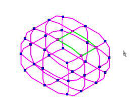
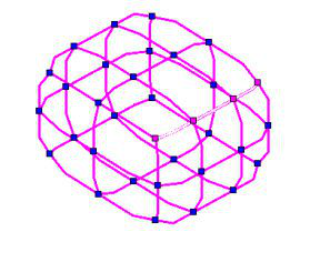
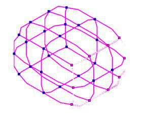
SMesh Crease
A crease is a sharp edge in an otherwise smooth surface. Creasing allows you to combine nice smooth curves with hard edges to make more realistic models. Any edge can be set to be creased. You cannot Crease if the Edit tool is in Selector Mode. The Crease value can be: -1, 0, 1, 2 or 3. A Crease value of 0 means No Crease. A Crease value of -1 means crease with no smoothing. Crease values from 1 to 3 interact with the Smoothness level. The values define the highest Smoothing Level at which the crease is retained. If the Smoothing Level exceeds this value of the crease, the crease is also smoothed. The degree of smoothing is one degree of for each level of difference between the Crease value and the Smoothing Level. For example: If the smooth level of the object is 4, and the Crease value is set to 1, the creased edge will have a effective Smoothness Level of 3.
 To crease edges, first select all of the edges you wish to crease.
 Once you have your edges selected specify the desired Crease value in the Inspector bar and press Enter.
Since selecting faces also selects their associated edges you can also begin your creasing by selecting faces for the desired edges. This can expedite maters in some cases.
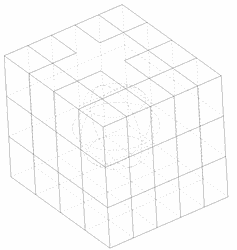
Re-patching
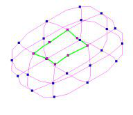
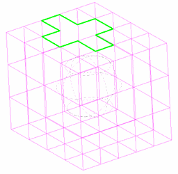
You can use a combination of merging, and refining to re-patch an area with an arrangement of faces that is more conducive to you desired results.
An important point to understand is that while they do opposite functions Merge and Refine are not direct inverses. In other words one does not undo the other. This example is going from merging faces to refining faces.
Another example is going from refining faces to merging faces.
Converting a SMesh
SMeshes can be converted from and to other forms, specifically Solids and TC Surfaces.
Booleans with SMesh
Boolean tools (Add, Subtract, Intersect, Slice) can be used on smeshes, so long as they are combined only with other smeshes or TC Surfaces. The result of any Boolean involving a smesh is a TC Surface. All of the facets of the smeshes and all of their Smoothing level subdivisions are converted to Facets on the resulting TC Surface. This can radically increase the number of apparent facets on the object.
Converting From a SMesh to a Solid
To convert a smesh into a Solid, just toggle the option in the 3D properties of the object. When converting from a TC Surface into a smesh, a set of facets will be generated from all of the facets of the smesh and all of its Smoothing level subdivisions. These are converted to Facets on the Solid. This can radically increase the number of apparent facets on the object, and generate some unpredictability of results. In many cases converting to a TC Surface first, then to a Solid will improve predictability.
Converting from a SMesh to a TC Surface
To convert a smesh into a TC Surface, just toggle the option in the 3D properties of the object. When converting from a TC Surface into a smesh all of the facets of the smesh and all of it Smoothing level subdivisions are converted to Facets on the TC Surface. This can radically increase the number of apparent facets on the object.
Converting Solid to SMesh
To convert a Solid into a smesh, just toggle the option in the 3D properties of the object. When converting from a Solid into a smesh, a set of facets will be generated to become facets on the smesh. This can result in unpredictable results. The following is an example of going directly from Solid to smesh.
You can improve the predictability by first converting the Solid to a TC Surface then to a smesh. The following is an example of going from Solid to TC Surface to smesh.
Changing between Solid and smesh for 3D primitives like a box will generally produces more predictable results as well.
Converting TC Surface to SMesh
To convert a TC Surface into a SMesh, just toggle the option in the 3D properties of the object. When converting from a TC Surface into a SMesh all of the facets of the TC Surface are converted to Facets on the SMesh.
Smesh Symmetry Tools

There are three Symmetry tools: Set Symmetry, Mirror Symmetry, and Remove Symmetry. The Set Symmetry and Mirror Symmetry tools are used to create a Mirror Symmetrical object from a Smesh. This means that only half of all points are available for editing. The points on the opposite side of the mirror are calculated automatically in accordance with mirror (plane of symmetry).
Set Symmetry
Default UI Menu: Modify/Modify 3D Objects/Surface Mesh/Set Symmetry
Ribbon UI Menu:
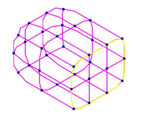
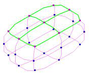
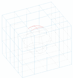
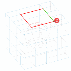
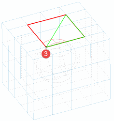
The tool looks for the "plane of symmetry" of the object. To use the Set Symmetry tool you must start with a symmetric object. This means there must be a natural division, equal on either side, and passing through edit nodes. For Example You can have a plane through the middle of a 4 wide mesh, but not through a three wide mesh because there are no edit nodes at the center.
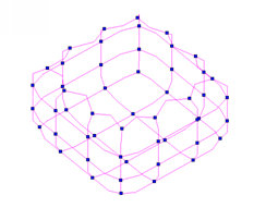
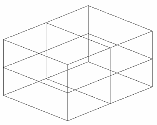
- Draw Smesh box
-
Explode it to create a Smesh object
-
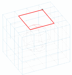
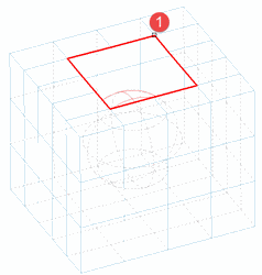
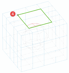
Click the Set Symmetry tool. As you move the mouse over the object acceptable planes will be highlighted. A series of points that are closed like this are sometimes referred to as loops.
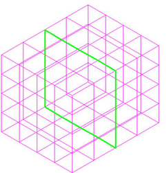
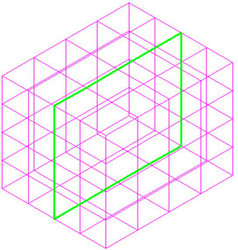
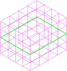
- Click to set the result .
Mirror Symmetry
Default UI Menu: Modify/Modify 3D Objects/Surface Mesh/Mirror Symmetry
Ribbon UI Menu:
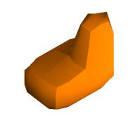
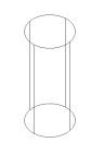
The Mirror Symmetry tool uses Smeshs which have an "open" boundary. An "Open boundary" is a hole in the closed object. To make an open boundary use the 3D Slice tool.
-
Draw a smesh box with the smooth level set to: None (This is important)
-
Explode the box
-
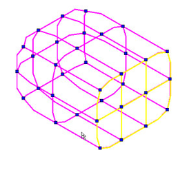
Select the 3D Slice tool.
- Slice the box.
-
The result should look like this.
-
Delete one of the resulting parts.
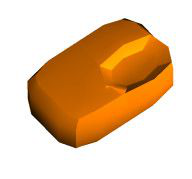
Now Proceed with Mirror Symmetry tool.
-
Select the "Mirror Symmetry" tool.
-
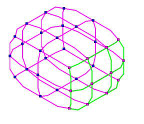
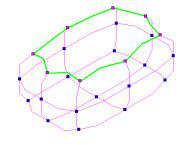
Hover over the sliced face.
-
Select the highlighted boundary.
-
The result should look something like this.
Remove Symmetry
Default UI Menu: Modify/Modify 3D Objects/Surface Mesh/Remove Symmetry
Ribbon UI Menu:

Delete Faces
Deletes selected faces from a Smesh. To delete faces:
-
Start the Edit tool.
-
Select the object.
- Select the faces you wish to delete.
- Disable "Selector mode" if it is enabled from local menu and then right click and choose Delete Facets from the local menu.
Copy Faces
Copies selected faces into a new smesh object. To Copy faces:
-
Start the Edit tool.
-
Select the object.
- Select the faces you wish to copy.
- Right click and choose Copy Facets from the local menu.
Add Face
Default UI Menu: Modify/Modify 3D Objects/Surface Mesh/Add Face
Ribbon UI Menu:

Adds a face to a smesh. The smesh must have a gap or hole in order to be modified.
 To add a face:
- Select the tool.
- Select the object.
- Draw the new face by selecting a series of points.
- Click Finish in the local menu or inspector bar.
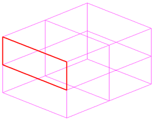
Split Face

Default UI Menu: Modify/Modify 3D Objects/Surface Mesh/Split face
Ribbon UI Menu:

Divide any face on a SMesh at any angle.
- Select a facet on the SMesh object.
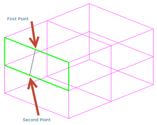
-
Select the first point to define the dividing line.
-
Select the second point to define the dividing line.
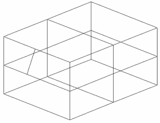
- The face is split.
Extrude Face
Default UI Menu: Modify/Modify 3D Objects/Surface Mesh/Extrude face
Ribbon UI Menu:

Extrude any face of a SMesh along a path defined by a Line, Arc, Polyline or Curve.
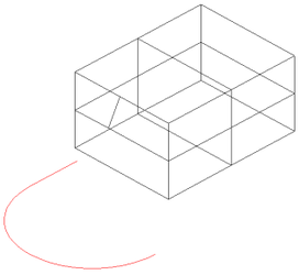
- Select a facet on the SMesh object.
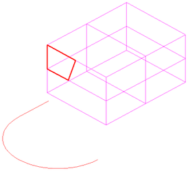
- Select the path defining object.
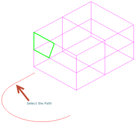
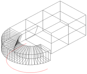
- The extrusion is created.
Split Face by Isoline
Default UI Menu: Modify/Modify 3D Objects/Surface Mesh/Split Face by Isoline
Ribbon UI Menu:

This tool splits all normal faces along a common isoline (a plane cutting through the object).
 To Split Faces:
-
Select the tool.
-
Hover over an edge of a face, the isoline will be drawn perpendicular to the edge.
- Click to split the faces along the isoline.
Note: Isolines do not cross merged faces.
Join Coplanar Faces
Default UI Menu: Modify/Modify 3D Objects/Surface Mesh/Join Coplaner Faces
Ribbon UI Menu:

Combines selected faces which share a common plane into a single face.
 To Combine faces:
-
Select the tool.
-
Select Faces.
- Click finish.
Options:
Use Neighbor Faces: When this option is on the resulting face will be formed from all faces on the object which are co-planar, and connected on that plane to the selected faces.
Merge Smesh
Default UI Menu: Modify/Modify 3D Objects/Surface Mesh/Merge Smesh
Ribbon UI Menu:

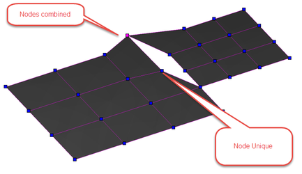
This tool combine two Smeshs into a single Smesh. The original Smeshs do not have to be touching or overlapping. Nodes that are coincident will be combined into a single node. To Merge Smeshs:
-
Select the Merge Smesh tool.
-
Click on the first smesh.
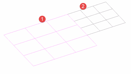
- Click on the second smesh.
Solidify
Default UI Menu: Modify/Modify 3D Objects/Surface Mesh/Solidify
Ribbon UI Menu:

This tool takes the surface of any smesh and adds depth to it. To solidify a smesh:
- Select the tool
- Specify the thickness desired.

- Click on the object.
- Click Finish
Keep Original:The original object is retained and the tool creates a new object.